Unequal length alternating hydraulic cylinder drive system for continuous material output flow with equal material output pressure

Inactive Publication Date: 2009-09-03
PUTZMEISTER AMERICA
View PDF16 Cites 23 Cited by
  • Summary
  • Abstract
  • Description
  • Claims
  • Application Information

AI Technical Summary

Benefits of technology

[0011]It is an additional object of the present invention to provide a hydraulically driven pumping arrangement for abrasive materials which offers improved performance, reliability and cost in installation and service.
[0012]The present invention relates to a hydraulically driven pumping system for delivering a compressible fluid material from a hopper to an outlet. The system includes a primary hydraulically driven pumping unit having a first interior volume for receiving the fluid material from the hopper. A secondary hydraulically driven pumping unit is interconnected with the primary pumping unit and has a second interior volume less than the first interior volume for receiving fluid material from the pr

Problems solved by technology

The mechanical pumping assembly can be variously driven by an engine or electric motor via a clutch, belts or chains, pulleys or sprockets, and a gearbox, all of which is undesirably complex.
The mechanical pumping assembly

Method used


Image

  • Unequal length alternating hydraulic cylinder drive system for continuous material output flow with equal material output pressure
  • Unequal length alternating hydraulic cylinder drive system for continuous material output flow with equal material output pressure
  • Unequal length alternating hydraulic cylinder drive system for continuous material output flow with equal material output pressure

Examples


Embodiment Construction

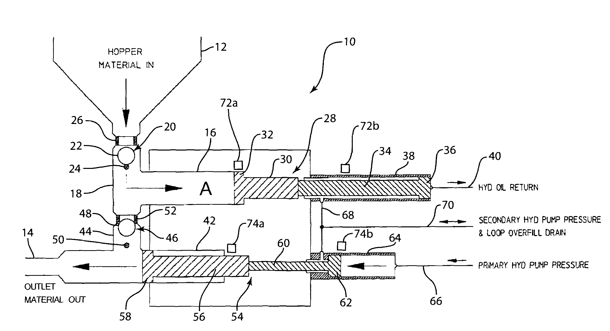
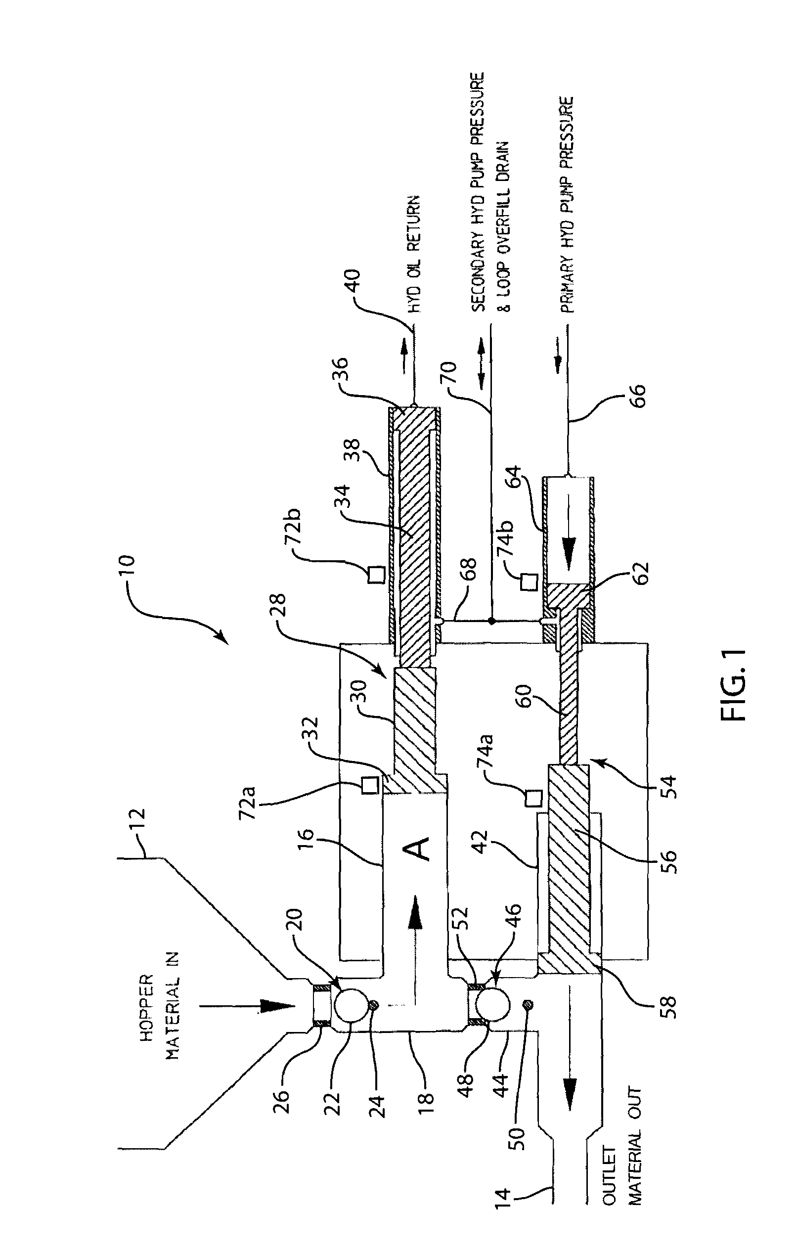
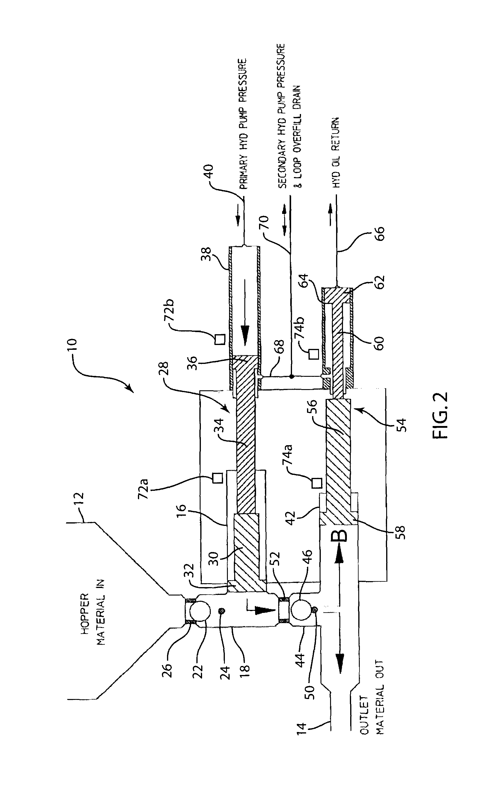
[0025]Referring to the drawings, a hydraulic cylinder drive system 10 forms a constant delivery pump used to provide a pressurized supply of abrasive, compressible fluid material, typically cement, plaster, mortar or the like, from a reservoir or hopper 12 to an outlet 14. Material delivered to the outlet 14 is normally directed to a spray nozzle for distribution to a desired surface, such as a building wall.

[0026]The system 10 includes a primary hydraulically driven pumping unit defined by a primary material cylinder 16 have a feed line 18 in communication within hopper 12 and an interior volume A at a head of the cylinder 16. A first one-way check valve 20 is positioned in feed line 18 between hopper 12 and primary material cylinder 16. The check valve 20 is a conventional mechanical design having a ball 22 movable between a stop 24 and a seat 26. The check valve 20 allows flow of material from hopper 12 into material cylinder 16 through the line 18, but blocks flow in the reverse...


PUM


Abstract

A hydraulic pumping system is provided for delivering a compressible fluid material from a hopper to an outlet. A primary hydraulically driven pumping unit has a first interior volume for receiving the fluid material from the hopper. A secondary hydraulically driven pumping unit is interconnected with the primary hydraulically driven pumping unit and has a second interior volume less than the first interior volume for receiving fluid material from the primary hydraulically driven pumping unit. The primary and secondary hydraulically driven pumping units have hydraulically driven reciprocating piston units with unequal stroke lengths. The piston units are alternately reciprocated to fill the first interior volume of fluid material from the hopper, pump a portion of the first interior volume of fluid material into the second interior volume and the remainder of the first interior volume to the outlet, and pump the second interior volume of fluid material to the outlet while fluid material is being pulled into the first interior volume in a sequential and simultaneous manner which will produce substantially continuous delivery of fluid material to the outlet.

Description

FIELD OF THE INVENTION[0001]The present invention relates generally to the field of pumps, and more particularly, pertains to a positive displacement pump arrangement designed to produce substantially continuous delivery of a compressible fluid material.BACKGROUND OF THE INVENTION[0002]Constant delivery fluid pumps find useful application in many fields. One field in which the pumps of this character are presently employed to advantage is the construction industry wherein it is relatively common practice to apply cement and plaster to building surfaces by means of spray nozzles. If a relatively uniform layer of plaster or cement material is to be applied to a building surface, the rate of flow of material from the spray nozzle of the spray unit must be relatively constant. This, in turn, requires a constant delivery pump capable of producing substantially a constant rate of material flow to the spray nozzle.[0003]Prior art pumps are, of course, known in the art, and are generally co...

Claims


Application Information

Patent Timeline
IPC IPC(8): F04B25/02F04B35/02
CPCF04B9/1095F04B15/023F04B11/0075
Inventor KRIVSKY, ANDREW J.SWEET, BRIAN G.
Owner PUTZMEISTER AMERICA
Why Eureka
Try Eureka