Chemical protection of metal surface

a metal surface and chemical protection technology, applied in the direction of electrolytic capacitors, cell components, capacitor electrodes, etc., can solve the problems of battery limitations, drop in charge and discharge capacity, and inability to meet the initial capacity of solid batteries,

Inactive Publication Date: 2009-09-03
RGT UNIV OF CALIFORNIA +1
View PDF12 Cites 17 Cited by
  • Summary
  • Abstract
  • Description
  • Claims
  • Application Information

AI Technical Summary

Problems solved by technology

Such batteries have limitations over repeated charge / discharge cycles and may have drops in their charge and discharge capacity over repeated cycles as compared to their initial charge and discharge capacity.
Additionally, an initial capacity of solid batteries is often less than desirable.
Another problem associated with electrochemical cells is the generation of dendrites over repeat charge and discharge cycles.
The dendrite may grow over repeated cycles and lead to a reduced performance of the battery or a short circuit not allowing the charge and discharge of the battery.

Method used


Image

  • Chemical protection of metal surface
  • Chemical protection of metal surface
  • Chemical protection of metal surface

Examples


example 1

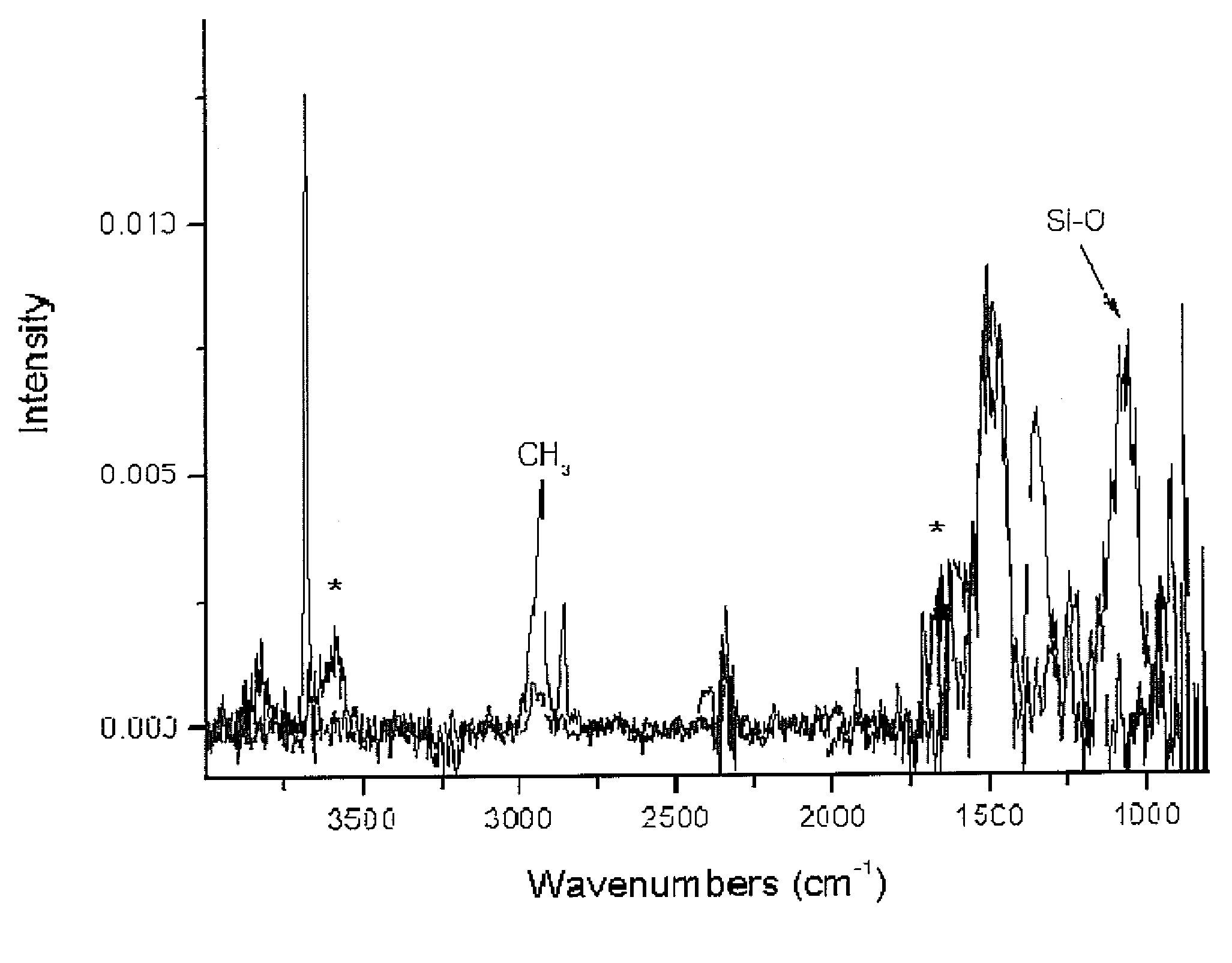
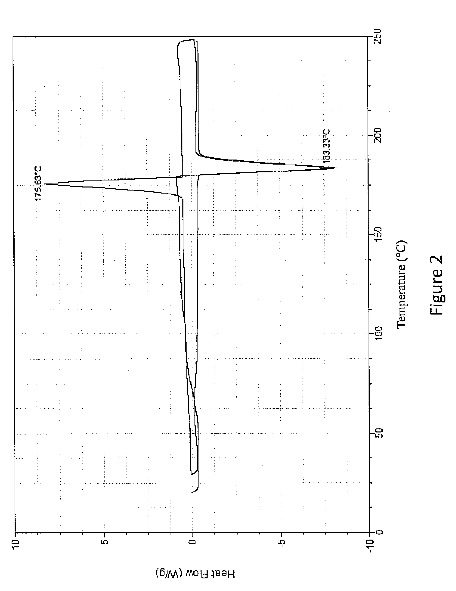
[0034]An untreated sample of the lithium metal and a sample treated with chlorotrimethyl silane for 240 seconds according to the above procedure were analyzed using IR spectroscopy, as shown in FIG. 1. The peak correspond to a lithium hydroxide bond is shown in the 3600 cm-1 range for the untreated sample. This peak is not shown for the treated sample which includes a peak in the 1100 cm-1 range corresponding to a silicon oxygen bond. This relationship indicates the precursor compound has reacted with the metal oxygen containing to form a silicon oxygen bond.

example 2

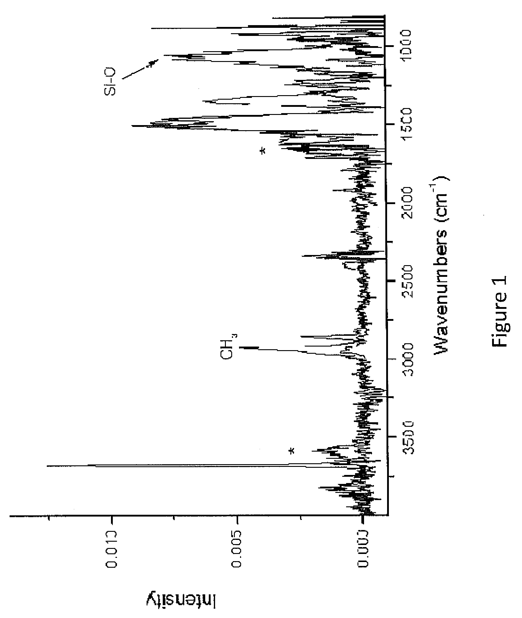
[0035]An untreated sample of the lithium metal and a sample treated with chlorotrimethyl silane according to the above procedure were analyzed using differential scanning calorimetry, as shown in FIG. 2. The samples were placed in aluminum pans with nitrogen gas flowing around the samples. The samples were heated to above the melting point and cooled below the melting point repetitively to determine whether the lithium was protected from the environment. The untreated lithium sample reacted with the aluminum pan and did not show melting and solidification representative of pure lithium metal. The treated sample, as shown in FIG. 2, exhibits very clear melting and solidification of lithium at or very near the melting point of lithium (the slight amount of superheating or supercooling at the melting point is heating rate dependent). The narrow peaks indicate that the lithium metal is protected and has not reacted with its environment in contrast to the unprotected sample.

example 3

[0036]Impedance tests were performed on various treated samples of lithium and untreated lithium as a reference. The experimental setup used is shown in FIG. 3. The various samples were formed using the procedure described above. The lithium samples were tested in the experimental setup with the sample placed in the positive electrode position. The impedance plots for various samples are shown in FIGS. 4-7. FIG. 4 shows the impedance plot for a sample treated with a chlorotrimethylsilane precursor forming a protective layer. FIG. 5 is a plot of the impedance for a chlorodiisopropylphosphine precursor forming a protective layer FIG. 6 is a plot of the impedance for a chlorodiethylphosphine precursor forming a protective layer. FIG. 7 is a plot of the impedance for a dibromodimethylborane precursor forming a protective layer. As can be seen in the figures the treated samples all have an impedance curve with a slope less than the reference samples. This behavior indicates an improved p...


PUM

PropertyMeasurementUnit
organo-metallicaaaaaaaaaa
IR spectroscopyaaaaaaaaaa
wavelengthaaaaaaaaaa

Abstract

An electrochemical cell includes an anode having a metal material having an oxygen containing layer. The electrochemical cell also includes a cathode and an electrolyte. The anode includes a protective layer formed by reacting a D or P block precursor with the oxygen containing layer.

Description

RELATED APPLICATION[0001]This application claims priority of U.S. patent application Ser. No. 11 / 457,525 filed Jul. 14, 2006, U.S. Provisional Patent Application Ser. No. 60 / 713,688 filed Sep. 2, 2005 and Ser. No. 60 / 739,499 filed Nov. 23, 2005, which are incorporated herein by reference.FIELD OF THE INVENTION[0002]The invention relates to chemical protection of a metal surface.BACKGROUND OF THE INVENTION[0003]Electrochemical cells containing a metallic anode, a cathode and a solid or solvent-containing electrolyte are known in the art. Such batteries have limitations over repeated charge / discharge cycles and may have drops in their charge and discharge capacity over repeated cycles as compared to their initial charge and discharge capacity. Additionally, an initial capacity of solid batteries is often less than desirable. There is therefore a need in the art for an improved battery having a high initial capacity and maintains such a capacity on repeated charge and discharge cycles....

Claims


Application Information

Patent Timeline
Patent Type & Authority Applications(United States)
IPC IPC(8): H01M4/60
CPCH01M4/134H01M4/1395H01M4/366H01M4/381H01M4/382H01M4/602Y02E60/122H01G9/042H01M4/40H01M4/405H01M4/62Y10T29/49108Y02E60/10H01M4/02H01G9/04C23C22/00
Inventor MENKE, ERIKUMEDA, GRANTDUNN, BRUCEWUDL, FREDRICHARD, MONIQUE N.STAMM, KIMBER L.
Owner RGT UNIV OF CALIFORNIA
Why Eureka
Try Eureka