System and Method for Alignment of Instrumentation in Image-Guided Intervention

a technology of image-guided intervention and system, applied in the field of system and method for aligning instruments in image-guided intervention, can solve the problems of difficult presentation, mental challenge, and large concentration, and achieve the effect of reducing the difficulty of presentation

Inactive Publication Date: 2009-09-03
PHILIPS ELECTRONICS LTD
View PDF12 Cites 191 Cited by
  • Summary
  • Abstract
  • Description
  • Claims
  • Application Information

AI Technical Summary

Benefits of technology

[0008]The invention addresses these and other difficulties in the art by providing a system, device, and methods for alignment and navigation of instrumentation during image-guided interventions. In some embodiments, a volumetric medical scan (image data) of a portion of the anatomy of a patient is loaded onto a computer that is connected to a tracking device capable of tracking the position and orientation of multiple position indicating elements in the tracking device's coordinate system. Patient space data regarding the anatomy of the patient may be obtained for example, using a registration device having one or more position indicating elements tracked by the tracking device. The patient space data is then registered to the volumetric image data.

Problems solved by technology

In all of these cases, difficulties may be presented.
This can be mentally challenging and require great concentration.
Unless he also preplans the path, he may be unaware of the material which will be transversed during the insertion of the device, potentially leading to complications if a critical anatomical structure is breached along the path.
Unfortunately, this type of view is not available though existing image guided surgery systems.
For these reasons and others, current techniques may pose many difficulties.

Method used


Image

  • System and Method for Alignment of Instrumentation in Image-Guided Intervention
  • System and Method for Alignment of Instrumentation in Image-Guided Intervention
  • System and Method for Alignment of Instrumentation in Image-Guided Intervention

Examples


Embodiment Construction

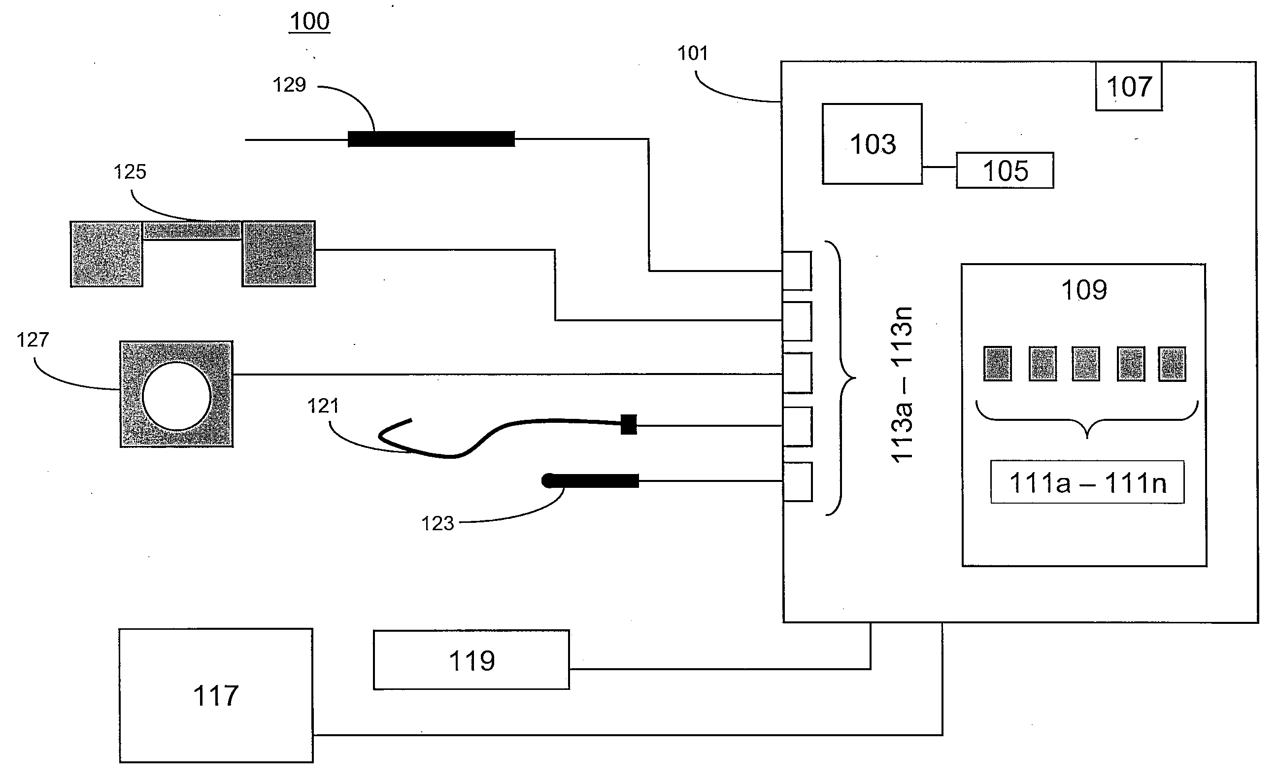
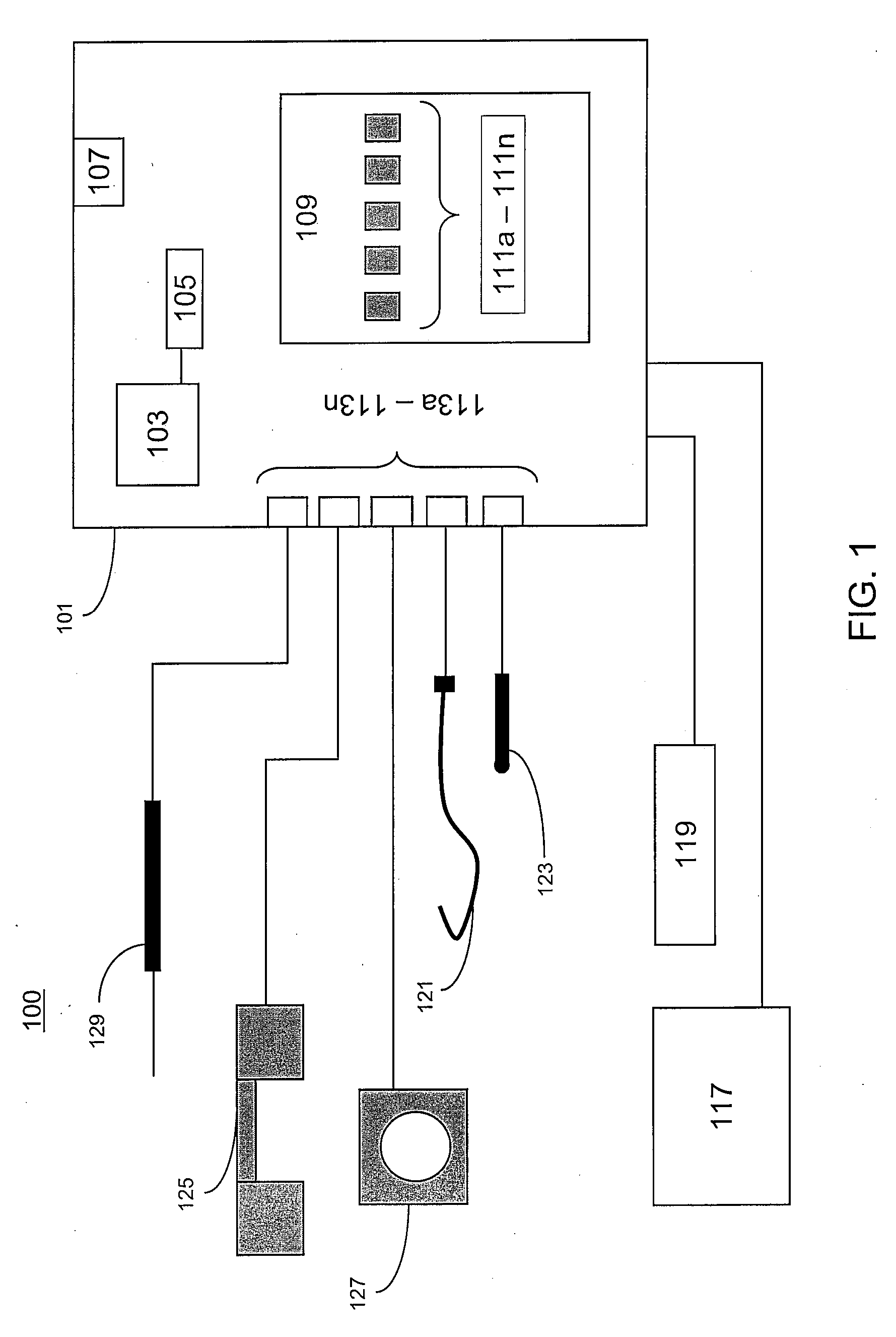
[0019]FIG. 1 illustrates a system 100, which is an example of a system for alignment and navigation of instrumentation during an image-guided intervention. System 100 may include a computer element 101, a registration device 121, an ultrasound simulator 123, a tracking device 125, an imaging device 127, a tracked instrument 129, and / or other elements.

[0020]Computer element 101 may include a processor 103, a memory device 105, a power source 107, a control application 109, one or more software modules 111a-111n, one or more inputs / outputs 113a-113n, a display device 117, a user input device 119, and / or other elements.

[0021]Computer element 101 may be or include one or more servers, personal computers, laptop computers, or other computer devices. In some embodiments, computer element 101 may receive, send, store, and / or manipulate data necessary to perform any of the processes, calculations, image formatting, image display, or operations described herein. In some embodiments, computer...


PUM


Abstract

The invention provides systems and methods for aligning or guiding instruments during image-guided interventions. A volumetric medical scan (image data) of a patient may first be registered to patient space data regarding the patient obtained using a tracking device. An ultrasound simulator fitted with position indicating elements whose location is tracked by the tracking device is introduced to the surface of the anatomy of the patient and used to determine an imaginary ultrasound scan plane for the ultrasound simulator. This scan plane is used to reformat the image data so that the image data can be displayed to a user in a manner analogous to a handheld ultrasound transducer by re-slicing the image data according to the location and orientation of the ultrasound simulator. The location of an instrument fitted with position indicating elements tracked by the tracking device may be projected onto the re-sliced scan data.

Description

FIELD OF THE INVENTION[0001]This invention relates to systems, methods, and instrumentation for facilitating accurate image-guided interventions using an ultrasound simulation device.BACKGROUND OF THE INVENTION[0002]When performing image-guided interventions (IGI), it is often required to guide a needle or instrument to a location in the body. In many forms of IGI, preoperative or intraoperative scans are performed. In some instances preoperative scans include computerized tomography (CT), magnetic resonance (MR), positron emission tomography (PET), or single proton emission tomography (SPECT). These modalities tend to utilize volumetric data acquisition, providing full 3D data sets comprising multiple “slices” of data representing contiguous or overlapping cross sections through the data.[0003]During an intervention, a physician may use a position sensing system (referred to herein as a “tracking device”) together with position indicating elements attached to individual instruments...

Claims


Application Information

Patent Timeline
Patent Type & Authority Applications(United States)
IPC IPC(8): A61B5/00
CPCA61B5/06A61B6/12A61B8/0833A61B17/3403A61B19/5244A61B2019/5295A61B2019/507A61B2019/5255A61B2019/5268A61B2019/5276A61B2019/5289A61B2017/3413A61B2034/2055A61B2034/2068A61B2090/367A61B34/20A61B2090/364A61B2034/107A61B2090/378A61B5/061A61B5/065A61B5/066A61B8/4245
Inventor GLOSSOP, NEIL DAVID
Owner PHILIPS ELECTRONICS LTD
Why Eureka
Try Eureka