Device for sustaining differential vacuum degrees for electron column

a technology of vacuum degree and electron column, which is applied in the direction of electrical equipment, electric discharge tubes, basic electric elements, etc., can solve the problems of increasing the cost of manufacturing the chamber to form ultra high vacuum, taking a long time to change samples, etc., and achieves the reduction of cost and time required for the manufacture and maintenance of equipment using the electron column, reducing the cost incurred, and saving time and cos

Inactive Publication Date: 2009-09-10
CEBT
View PDF21 Cites 4 Cited by
  • Summary
  • Abstract
  • Description
  • Claims
  • Application Information

AI Technical Summary

Benefits of technology

[0021]Thanks to the above features, the device for sustaining different vacuum degrees for an electron column according to the present invention provides advantages in that an ultra high vacuum (UHV) for allowing electrons to be easily emitted from the electron emitter of an electron column can be formed in a minimal space, and the vacuum degree for electron column which is different from the vacuum degree for a sample on which an electron beam is incident can be easily realized. As a consequence, the cost and time required for the manufacture and maintenance of the equipment using the electron column can be reduced.
[0022]Also, since a bake-out time can not be required in addition to reducing the cost incurred to form the ultra high vacuum, when changing a sample, the time and the cost can be further saved. In particular, in terms of time, it is possible to quickly change or replace a sample in a short time. Further, the costs incurred when using a large-sized ion pump or getter pump and forming a chamber so as to induce an ultra high vacuum in a large space can be significantly saved.
[0023]When using an electron column, if it is required to induce a different vacuum degree, the device according to the present invention can be used in a simple and easy manner.

Problems solved by technology

In this regard, if the electron column and the sample are employed in an ultra high vacuum, it takes a long time to change a sample, and the cost of manufacturing the chamber to form the ultra high vacuum increases.
That is to say, it is not preferable to maintain the chamber, in which the sample is placed to allow the electron beam emitted from the electron column to be incident thereon, in an ultra high vacuum state, because substantial costs are incurred.

Method used


Image

  • Device for sustaining differential vacuum degrees for electron column
  • Device for sustaining differential vacuum degrees for electron column
  • Device for sustaining differential vacuum degrees for electron column

Examples


Embodiment Construction

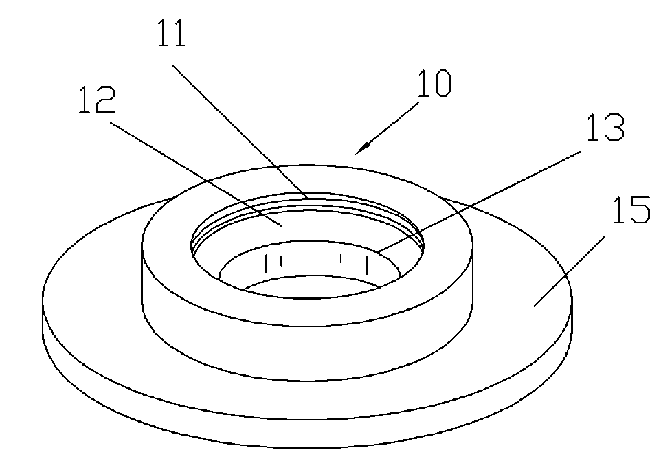
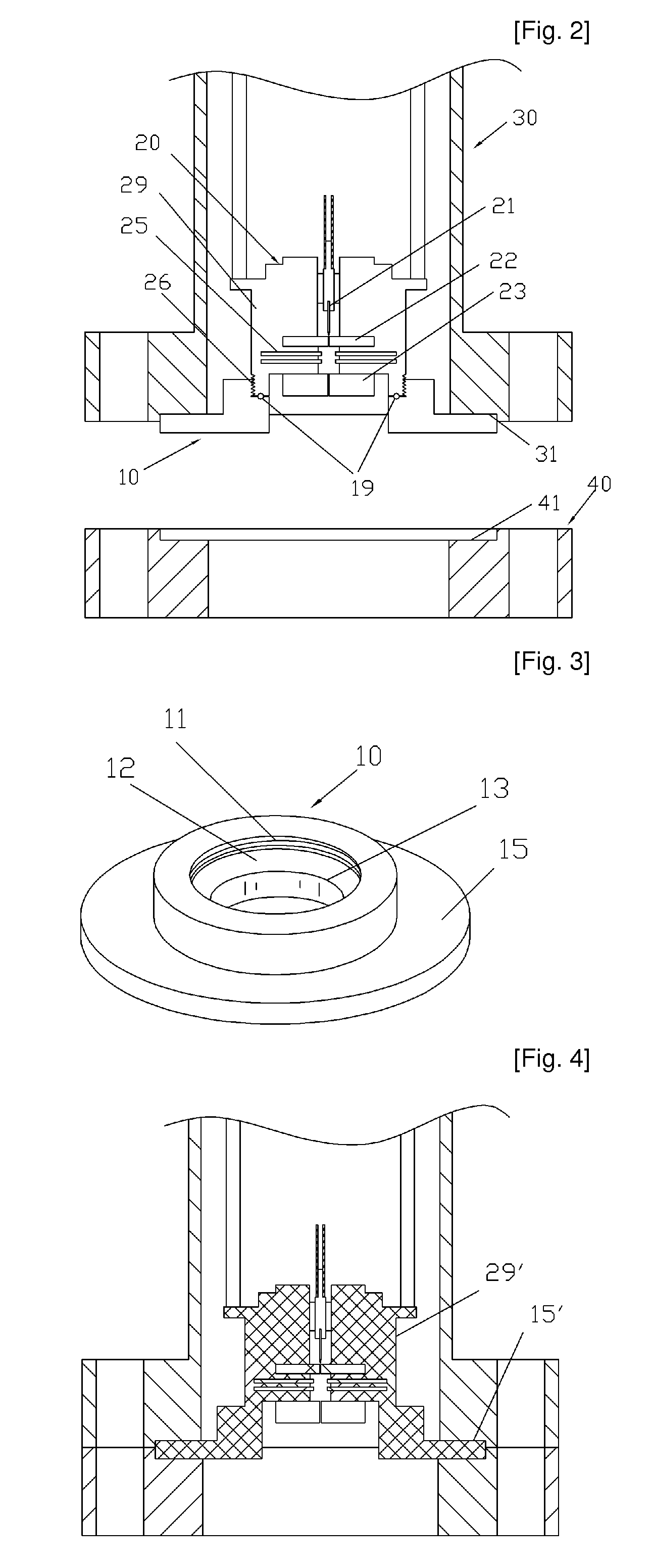
[0033]Reference will now be made in greater detail to a preferred embodiment of the invention, an example of which is illustrated in the accompanying drawings. First, one embodiment of the present invention will be described with reference to FIGS. 2 and 3. FIG. 2 illustrates a state in which a device 10 for sustaining different vacuum degrees for an electron column in accordance with an embodiment of the present invention is used in a state in which it is coupled to the housing of an electron column in a 4-way˜6-way crosses or a cubic chamber, etc. serving as a chamber 30 for an electron column 20. A column housing 29, in and to which an electron emitter 21, lens parts 22 and 23, deflectors 25, and so forth are inserted and coupled as component parts of the electron column, and the device 10 for sustaining different vacuum degrees according to the present invention, are coupled with each other, and the resultant structure is received in the gasket accommodation part 31 of the chamb...


PUM


Abstract

Disclosed is a device for sustaining different vacuum degrees for an electron column, including an electron emitter, a lens part, and a housing for securing them, to maintain the electron column and a sample under different vacuum degrees. The device comprises a column housing coupling part coupled to the housing to isolate a vacuum; a hollow part defined through the center portion of the device to allow an electron beam emitted from the electron column to pass therethrough; and a vacuum isolation part having a structure of a gasket for vacuum coupling, wherein a difference of no less than 10 torr in a vacuum degree is maintained between both sides of the device by selecting an appropriate diameter of a lens electrode layer which is finally positioned in a path along which the electron beam is emitted or by using the hollow part.

Description

TECHNICAL FIELD[0001]The present invention relates to a device for sustaining different vacuum degrees for an electron column, and more particularly, to a device for sustaining different vacuum degrees for an electron column, which maintains the vacuum degree of a chamber in which an electron column is used and the vacuum degree of a chamber in which a sample is placed different from each other.BACKGROUND ART[0002]As is generally known in the art, an electron column is used to generate an electron beam by emitting electrons. A microcolumn is a very small electron column constructed by miniaturizing an electron column, which uses a principle of controlling an electron beam conventionally employed in a CRT, in an electron microscope, for electron beam lithography, and in various electron beam apparatuses.[0003]FIG. 1 illustrates the structure of a microcolumn 100 as a typical very small electron column. The microcolumn 100 includes, as its basic component parts, an electron emitter 11...

Claims


Application Information

Patent Timeline
Patent Type & Authority Applications(United States)
IPC IPC(8): H01J33/00
CPCH01J37/18H01J2237/188H01J2237/1205H01J37/147
Inventor KIM, HO SEOB
Owner CEBT
Why Eureka
Try Eureka