Display apparatus for displaying an image

a technology for display apparatus and images, applied in the field of image display apparatus, can solve the problems of uneven luminance, difficult cooling of high temperature components implemented on the substrate, and insufficient cooling of components, etc., and achieve the effects of slimming down the apparatus, increasing the area of the panel module, and improving the cooling

Active Publication Date: 2009-09-10
MAXELL HLDG LTD
View PDF17 Cites 31 Cited by
  • Summary
  • Abstract
  • Description
  • Claims
  • Application Information

AI Technical Summary

Benefits of technology

[0021]According to the above-described aspect of the present invention, the strength of the image display apparatus is sufficiently secured while slimming down the apparatus. Also, the high heat temperature components are favorably cooled while slimming down the apparatus.
[0022]Also, according to the aspect of the present invention, an excellent advantage is obtained in which the problem caused by an increase in the area of the panel module due to upsizing of the image display apparatus is solved, that is, in which a panel module with excellent mechanical strength is manufactured with ease and a low cost and therefore an image display apparatus suitable for upsizing or slimming down is provided.
[0023]Thus, the case is used as a heat dispersion member and the first space between the circuit and case is reduced to the minimum without increasing the first space so that cooling of the high heat temperature components (radiation of heat) is efficiently performed. On the other hand, since the second space between the back surface of the panel module and the substrates is made larger than the first space, thermal interference between the high temperature components and the backlight unit of the panel module is reduced so that a sufficient air flow is secured between the back surface of the panel module and the substrates. Thus, the high temperature components are more favorably cooled.

Problems solved by technology

However, as slimming down of the image display apparatus proceeds as described above, the passage of air is narrowed so that these components are not sufficiently cooled.
This makes it difficult to cool the high temperature components implemented on the substrates.
This results in luminance unevenness.

Method used


Image

  • Display apparatus for displaying an image
  • Display apparatus for displaying an image
  • Display apparatus for displaying an image

Examples


Embodiment Construction

[0034]Now, an embodiment of the present invention will be described in detail with reference to the accompanying drawings. In these drawings, components having same functions are given same reference numerals and will not be repeatedly described.

[0035]Hereafter, an image display apparatus according to this embodiment using a liquid crystal display (LCD) as a large-size display will be described together with a supporting structure thereof.

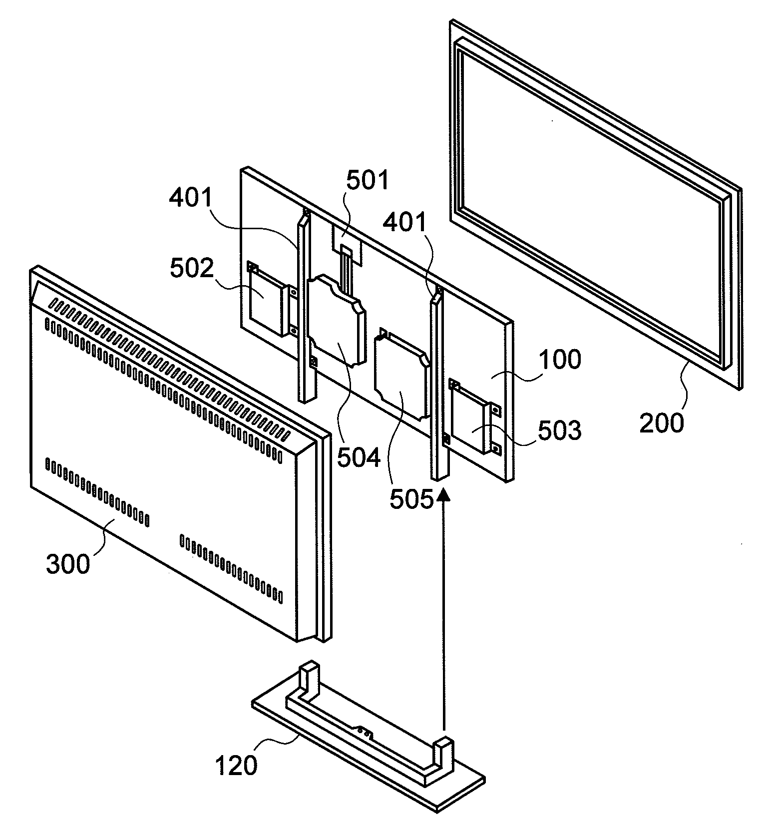
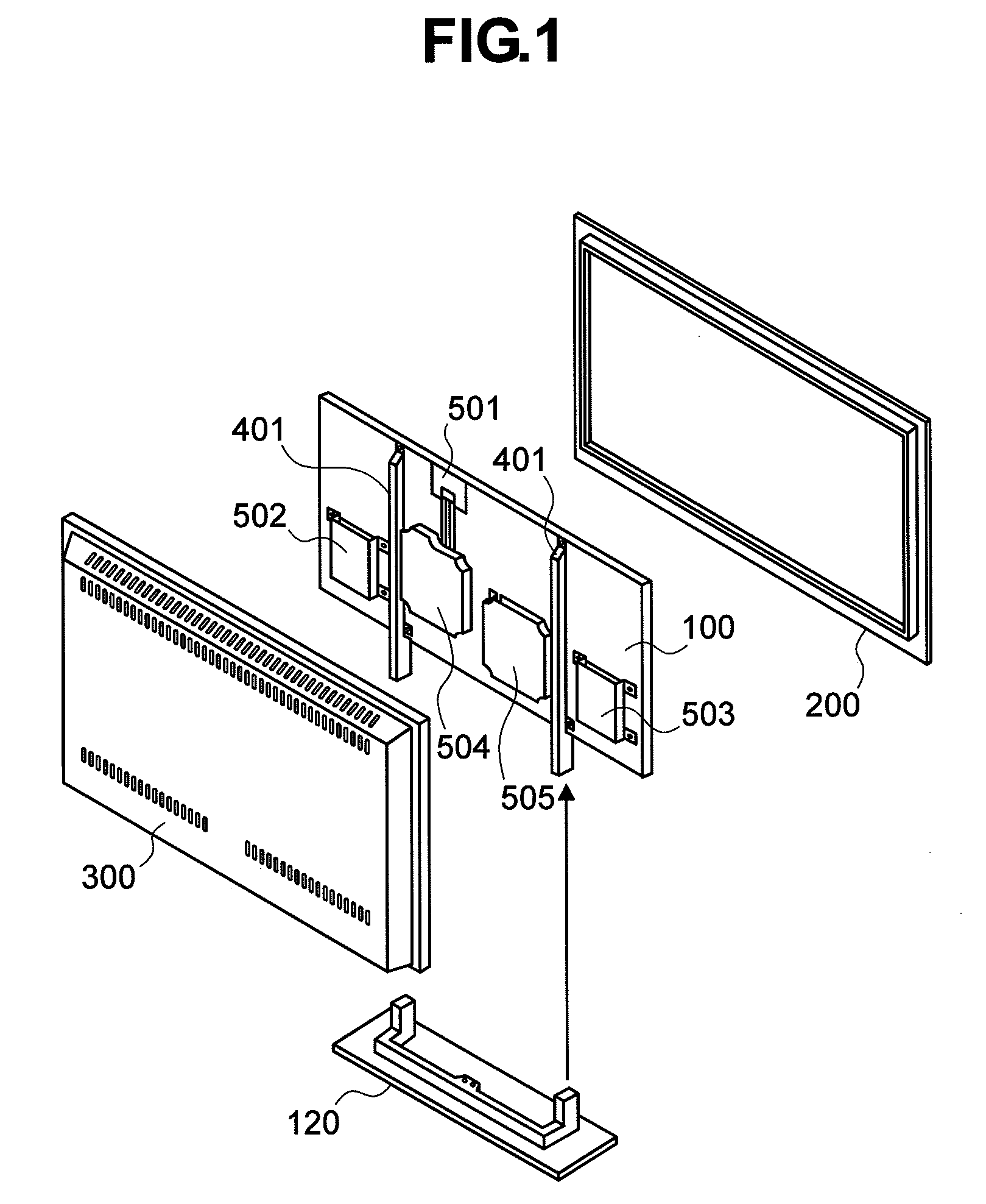
[0036]FIG. 1 is a developed view showing an overall configuration of the image display apparatus according to this embodiment. In FIG. 1, reference numeral 100 represents an LCD as a large-size display. The LCD 100 is typically mounted on an opening of a frame obtained by forming a thin metal plate made of iron or aluminum into a box shape with a shallow bottom and a large area. Hereafter, the LCD 100 will be referred to as a panel module 100. For example, multiple fluorescent tubes or a light emitter including a light-emitting diode and the like a...


PUM


Abstract

To provide an image display apparatus that is allowed to incorporate a panel module with excellent mechanical strength even if a screen is upsized and the apparatus is slimmed down. Strengthening units are mounted along a horizontal direction on canopies provided on an upper portion and a lower portion of a panel module constituting a display unit of a large-size, thin image display apparatus. Also, supporting members are mounted on the upper and lower strengthening units in such a manner that the supporting members bridge between the upper and lower strengthening units, so that a stand, or a chain or a string to be used when hanging the image display apparatus is mountable to the supporting members. This prevents direct application of external force to the panel module.

Description

BACKGROUND OF THE INVENTION[0001](1) Field of the Invention[0002]The present invention relates to an image display apparatus using a flat panel display (FDP) such as a liquid crystal display (LCD) or a plasma display panel (PDP). In particular, the invention relates to a supporting or strengthening structure of a panel module using an FDP.[0003](2) Description of the Related Art[0004]As television programs are broadcast digitally and with higher resolutions in recent years, there has been required a large-size (large screen), thin image display apparatus for, as a television set, receiving a broadcast or rebroadcast television program using an external or built-in tuner and displaying the received television program. As such large-size, thin image display apparatuses, ones using an FPD such as a LCD, a PDP, or an organic electro-luminescence (OEL) panel, as well as conventional projection display apparatuses have come on the market. Various supporting structures of such large-size, ...

Claims


Application Information

Patent Timeline
Patent Type & Authority Applications(United States)
IPC IPC(8): H04N5/64G09G3/36
CPCH05K5/02H04N5/64
Inventor SUZUKI, YASUHIKOYAMAGUCHI, KATSUMIKAKU, NOBUYUKI
Owner MAXELL HLDG LTD
Why Eureka
Try Eureka