
Micro-transducer with improved perceived sound quality

Inactive Publication Date: 2009-09-10
BANG & OLUFSEN ICEPOWER
View PDF42 Cites 12 Cited by
  • Summary
  • Abstract
  • Description
  • Claims
  • Application Information

AI Technical Summary

Benefits of technology

"The present invention provides a new micro-transducer technology for small acoustic back enclosures, such as mobile phones, that improves sound quality, attainable sound pressure levels, and the bandwidth of the transducer while reducing non-linear distortion. The micro-transducer has a very soft mechanical suspension that needs the stiffness provided from the air sealed in a small closed back volume to obtain a proper damping of diaphragm movement. The non-circular design of the micro-transducer ensures a powerful force exerted on the diaphragm combined with the soft suspension, which makes it suitable for small back volumes. The invention also provides a method of optimizing the qualitative attributes of a sound reproduction device by providing a micro-transducer with a compliance above the compliance required for optimizing the frequency response and resonance frequency of the device and mounting the transducer on the device so that the diaphragm and suspension means of the transducer are in fluid communication with an internal volume (back volume) of the device."

Problems solved by technology

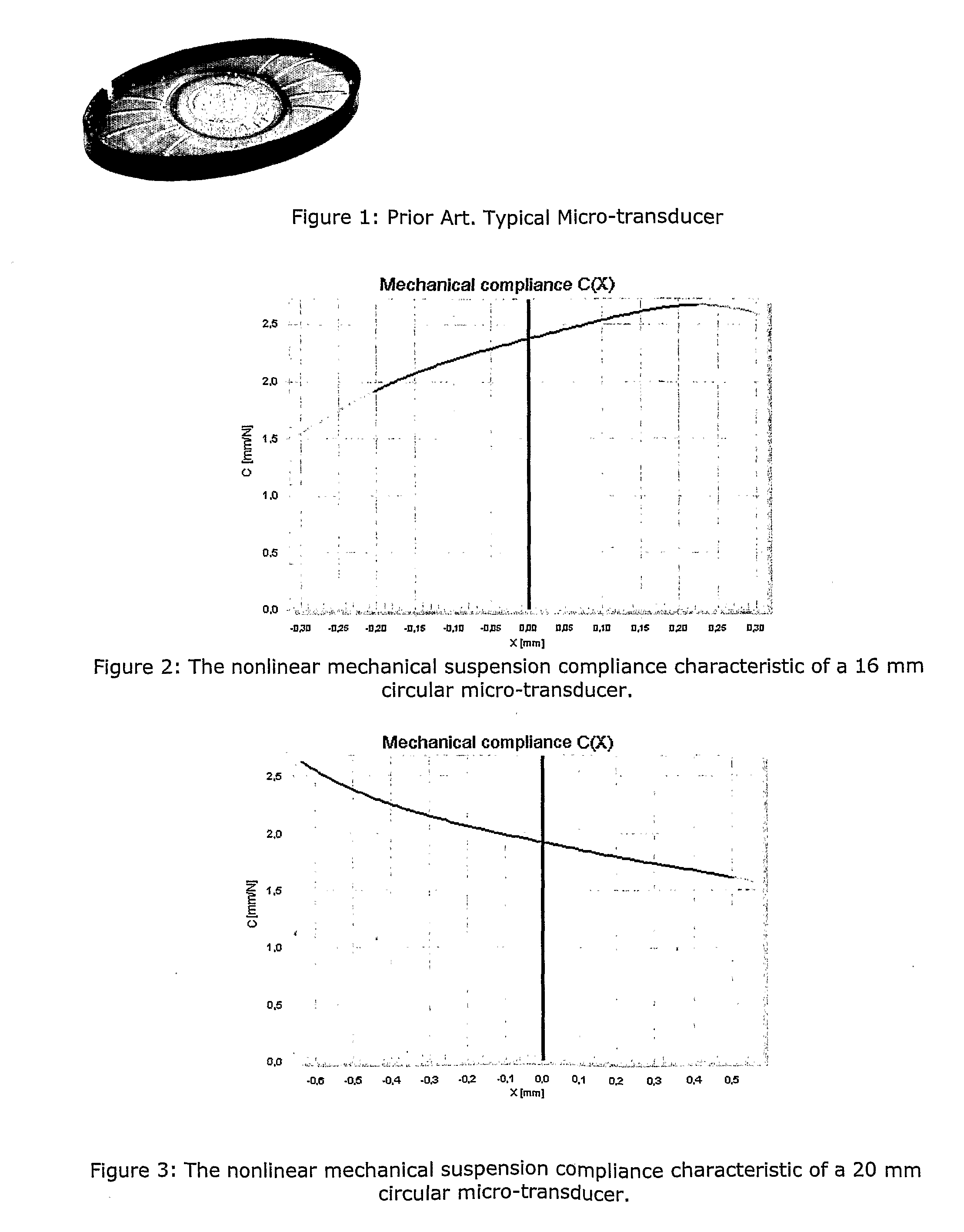
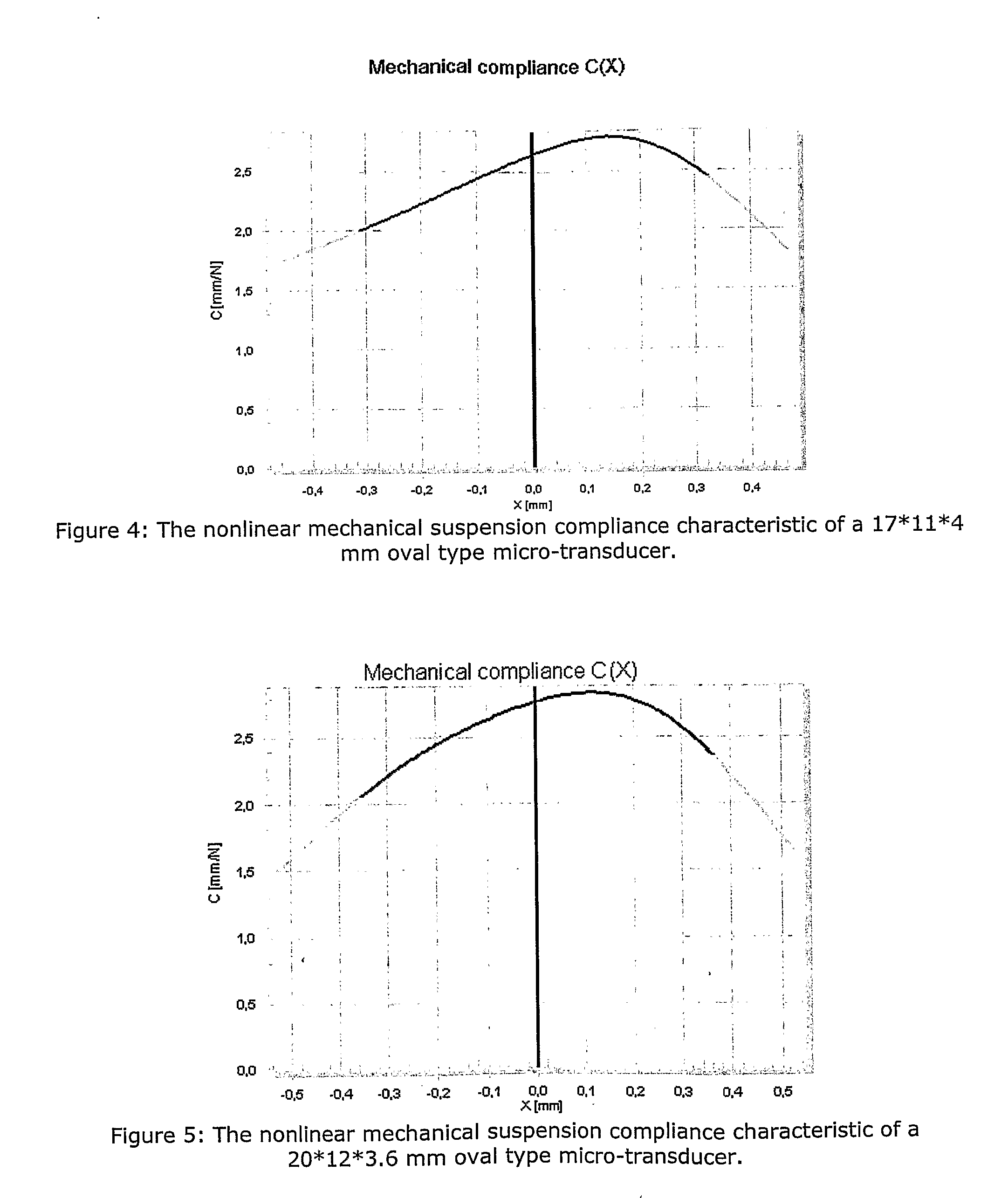
The typical prior art micro-transducer offers high sensitivity and low cost; however the following problems are generally observed:The magnet system is non-linear, i.e. the force factor BI(x) depends significantly upon displacement x, causing distortion.Due to the design of the circularly shaped magnet system (voice coil, center top plate, magnet, back plate, etc.), the force factor is, besides being non-linear, also quite low and asymmetrical, resulting in lower driving force and greater distortion.The suspension system is non-linear and asymmetrical, i.e. the compliance C(x) varies with excursion, causing distortion.The diaphragm has under-damped resonances, causing frequency response degradation (notch filter effects) and distortion within the audio band, resulting in a resonant distortion exhibiting very high values at certain frequencies.The suspension compliance characteristics [m / Newton] of typical micro transducers do not fit well with small cabinet volumes, since the air compliance in the back enclosure will enlarge diaphragm and suspension break-up effects.
This will lead to a very high and undesirable resonance frequency of the total reproduction system when such micro-transducers are mounted in a housing with small back volumes.
This will lead to a very poor performance when they are mounted in small back volumes because the total compliance from the mechanical suspension and from the air in the back volume will be unnecessary low.
From these measured characteristics it can be seen that the generally thin transparent plastic used as suspension is quite non-linear and asymmetrical, which causes both even and odd harmonic distortion.
This unfortunately introduces distortion both from the suspension and the force factor.
A second disadvantage of the thin transparent plastic is that the membrane breaks up, especially at high outputs with small back enclosures, causing significant distortion increase and sound pressure level (SPL) reduction (the suspension and diaphragm often have the same thickness and also often consist of the same material).
A final negative effect of the suspension system is the reduction of effective diaphragm area.
From the analysis of different micro-transducers it is concluded that the compliance characteristics do not necessarily improve with size and depth, as such improvement is not gained by size.
The limitations are within the transducer architecture / design itself.
This results in a weak driving Lorentz force and in higher total harmonic distortion.
The main reason for the resonant and frequency dependent distortion characteristics is the uncontrollable diaphragm and suspension, which breaks up at high frequencies, causing an unpleasant high frequency reproduction.
This is mainly due to small compliance from the small back enclosure combined with the 100 mW input, resulting in large internal sound pressure in the housing at low frequencies.
Above 1 KHz the amount of distortion is excessive, and because the human ear has the highest sensitivity in the 1 kHz to 4 kHz range, this is very undesirable and will lead to a harsh and unclear sound impression.

Method used


Image

  • Micro-transducer with improved perceived sound quality
  • Micro-transducer with improved perceived sound quality
  • Micro-transducer with improved perceived sound quality

Examples


Embodiment Construction

[0071]In the following a detailed description of embodiments of the micro-transducer according to the invention is given, but it is to be understood that the invention is not limited to the shown embodiments.

[0072]Referring to FIG. 14, there is shown an SSL Transducer Prototype according to the invention, basically comprising a large, rigid diaphragm portion 2 and an optimised soft suspension 3. The embodiment shown in FIG. 14 is of a substantially oval configuration, but other configurations could also be used, for instance dependent on the final application.

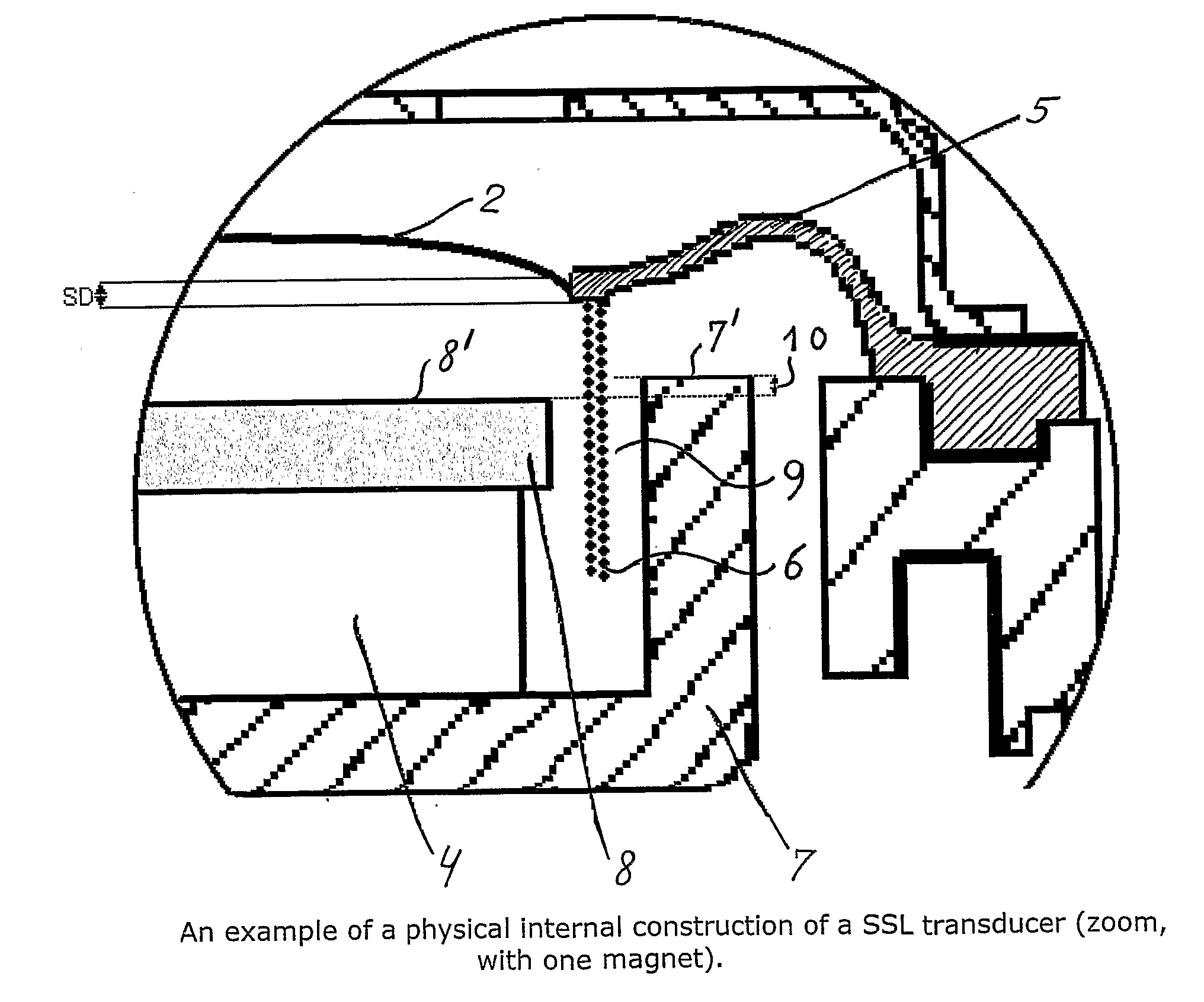
[0073]Referring to FIG. 15, there is shown an SSL Micro-transducer architecture according to an embodiment of the invention (with one magnet 4) with means for optimised soft suspension 5, a large rigid diaphragm 2, a long throw voice coil design 6 and the large magnetic force mechanism comprising the magnet 4 and the associated pole pieces 7, 8.

[0074]A description of how an SSL micro transducer's physical architecture could be ...


PUM


Abstract

The typical micro-transducer dedicated for mobile phones and headphones produces at high output in small back enclosure significant distortion in the acoustical output. These typical micro-transducers are designed for very high sensitivity and their mechanical suspension compliances are designed for worst case scenario, free air environment or a very large back enclosure (were the air stiffness from the back enclosure is much lower than the mechanical transducer suspension stiffness). This leads to poor low frequency response, high distortion, non-linear SPL characteristic and unnecessary high system resonance fre-quency when the transducer is placed in a small back enclosure. The Soft Suspension Long throw (SSL) micro-transducer has been designed with an improved non-circular shaped magnetic system, a low density / high Young's modulus thermal conducting diaphragm, a large-area non-circularly shaped diaphragm area, a non-circular shaped voice coil and a soft long-throw suspension which has been designed so that the SSL micro-transducer only functions properly when mounted in a small back enclosure. The combination of these inventions leads to a transducer architecture offering significant improvements in overall distortion, high RMS power handling, extended bass reproduction, also in compact volumes, and an overall flat frequency response. The combined result of several inventions is a significant overall improvement in perceived sound quality.

Description

TECHNICAL FIELD[0001]The present invention relates generally to methods and products for use in optimising the qualitative attributes of a small sound system, such as a mobile phone or head phone, and more specifically to the design of micro sound emitting transducers, such as loudspeakers, aiming at optimising qualitative attributes of such transducers. The invention also relates to audio devices provided with such transducers and to a method for optimising acoustical performance (for instance sound quality) of such devices.BACKGROUND OF THE INVENTION[0002]Micro-speakers are used widely in mobile phones today for audio reproduction, hands free speech, etc. Besides the desire for a high sound pressure level, there is an increasing demand for high quality audio reproduction.[0003]The typical micro-transducer architecture is illustrated in FIG. 1. An oval type is shown for reference; however a range of alternatives exists (round, square, etc.), and such micro-transducers can furthermo...

Claims


Application Information

Patent Timeline
Patent Type & Authority Applications(United States)
IPC IPC(8): H04R1/20H04R9/06
CPCH04R1/22H04R7/125H04R2499/11H04R2400/11H04R9/025H04R2307/027
Inventor NIELSEN, KARSTENHANSEN, LARS BRANDT ROSENDAHL
Owner BANG & OLUFSEN ICEPOWER
Learn More