Methods and apparatus for reconfigurable add drop multiplexers

a technology of add drop multiplexers and reconfiguration methods, which is applied in multiplex communication, instruments, optical elements, etc., can solve the problems of increased input-to-output insertion loss of input signals, complex design and construction of large wavelength selective switches, and inability to provide all inputs of each wss device, etc., to achieve less insertion loss and less insertion loss

Active Publication Date: 2009-09-10
TELLABS OPERATIONS
View PDF27 Cites 60 Cited by
  • Summary
  • Abstract
  • Description
  • Claims
  • Application Information

AI Technical Summary

Benefits of technology

[0011]A corresponding method of processing optical signals with a first ROADM includes enabling a first add port to receive an optical signal from a second ROADM with less insertion loss than receiving the same optical signal through a second add port. The corresponding method also includes transmitting an optical signal through a first drop port to the second ROADM with less insertion loss than transmitting the same optical signal through a second drop port. The method may be used in an optical system that includes a first ROADM that has a plurality of add and drop ports and a second ROADM optically coupled to the first ROADM through an add port and a drop port of the first ROADM.

Problems solved by technology

A large wavelength selective switch (WSS) can be complex and costly to design and construct.
However, when one cascades the smaller WSS devices, not all of the inputs of each of the WSS devices are available be used as inputs to the overall 11×1 WSS, as some inputs of some smaller WSS devices are used to connect one smaller WSS device to another smaller WSS device.
Furthermore, some input signals to the 11×1 WSS may traverse multiple smaller WSS devices before exiting the 11×1 WSS, resulting in increased input-to-output insertion loss for those input signals.

Method used


Image

  • Methods and apparatus for reconfigurable add drop multiplexers
  • Methods and apparatus for reconfigurable add drop multiplexers
  • Methods and apparatus for reconfigurable add drop multiplexers

Examples


Embodiment Construction

[0041]A description of example embodiments of the invention follows.

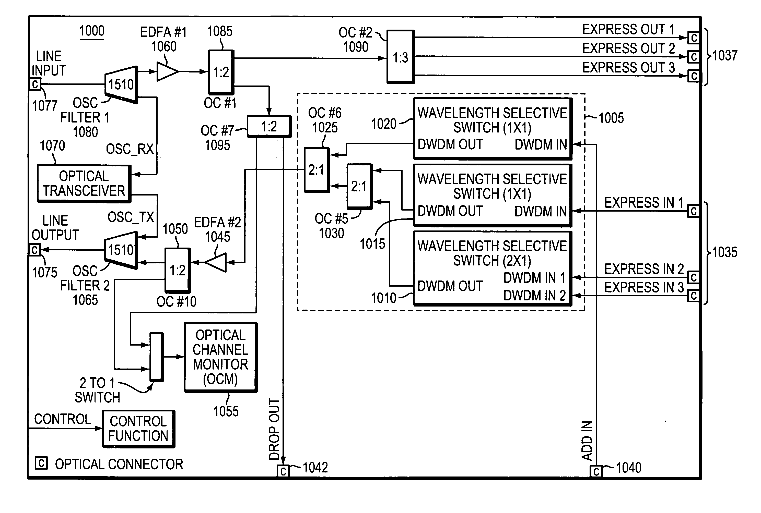
[0042]Unless otherwise noted, all optical amplifiers may have gain that is fixed, variable, adjustable, programmable, or any combination thereof. Optical attenuators, including variable optical attenuators (VOAs), may optionally be placed in front of the fixed gain amplifier. Optical amplifiers may be erbium-doped fiber amplifiers, solid-state optical amplifiers, or any other suitable optical amplifiers. Optical characteristics, including gain, saturated output power, and noise figure, may depend on system requirements including, but not limited to, propagation loss, insertion loss, maximum optical power, minimum optical power, and system cost.

[0043]Similarly, unless otherwise noted, VOAs may be individual discrete VOAs, arrays of VOAs residing on a single silicon die (or other suitable substrate material), or any other suitable attenuator(s). Likewise, tunable filters may be individual discrete tunable filters, or ...


PUM


Abstract

Optical networks are increasingly employing optical network nodes having multiple interfaces to allow a node to direct optical signals received at any interface to any other interface connected to the node. Constructing a larger wavelength selective switching (WSS) module used in such a node can be complex and expensive. A method an apparatus for constructing a large WSS using parallelism is provided. In example embodiments, a larger WSS may include multiple parallel non-cascaded smaller WSSs and an optical coupler configured to optically couple the multiple parallel, non-cascaded smaller WSSs. This technique may be used to construct both N×1 and 1×N WSSs. Because the technique employs multiple parallel, non-cascaded WSSs, all inputs of a larger N×1 WSS and all outputs of a larger 1×N WSS are available receive or transmit external signals rather than being rather than being unavailable due to, for example, cascading smaller WSS devices together.

Description

RELATED APPLICATIONS[0001]This application claims the benefit of: U.S. Provisional Application No. 61 / 188,083, filed on Aug. 6, 2008; U.S. Provisional Application No. 61 / 072,584, filed on Apr. 1, 2008; U.S. Provisional Application No. 61 / 070,573, filed on Mar. 24, 2008; U.S. Provisional Application No. 61 / 069,947, filed on Mar. 19, 2008; U.S. Provisional Application No. 61 / 069,825, filed on Mar. 17, 2008; and U.S. Provisional Application No. 61 / 068,277, filed on Mar. 5, 2008.[0002]The entire teachings of the above applications are incorporated herein by reference.BACKGROUND OF THE INVENTION[0003]A large wavelength selective switch (WSS) can be complex and costly to design and construct. Multiple smaller WSSs can be lower in cost than one equivalently sized large WSS. A known method of creating a larger WSS device from multiple smaller WSS devices involves daisy chaining or cascading smaller WSS devices to create a larger WSS device.[0004]For example, an 11×1 WSS can be created by ca...

Claims


Application Information

Patent Timeline
Patent Type & Authority Applications(United States)
IPC IPC(8): H04J14/00
CPCH04J14/0204G02B6/293H04J14/0206H04J14/0208H04J14/0209H04J14/021H04J14/0212H04J14/0213H04J14/0217H04J14/0219H04J14/0221H04J14/0227H04J14/0282H04J14/0283H04J14/0284H04Q11/0005H04Q2011/0015H04Q2011/0016H04Q2011/0032H04Q2011/0052H04J14/0205
Inventor BODUCH, MARK E.
Owner TELLABS OPERATIONS
Why Eureka
Try Eureka