
Efficiency enhancement and protection method for ocean, river and channel kinetic hydro turbines

a technology of kinetic hydro turbines and enhancement and protection methods, which is applied in the direction of motors, sea energy generation, tidal streams/damless hydropower, etc., can solve the problems of large wake zones and achieve the effect of maximizing the effect of the obj

Inactive Publication Date: 2009-09-10
BIBEAU ERIC L +1
View PDF20 Cites 21 Cited by
  • Summary
  • Abstract
  • Description
  • Claims
  • Application Information

AI Technical Summary

Benefits of technology

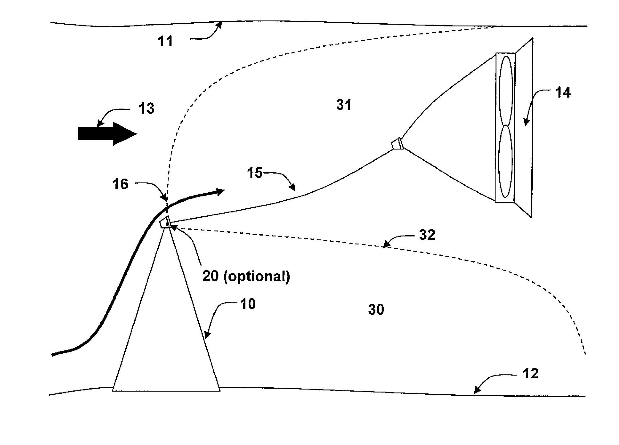
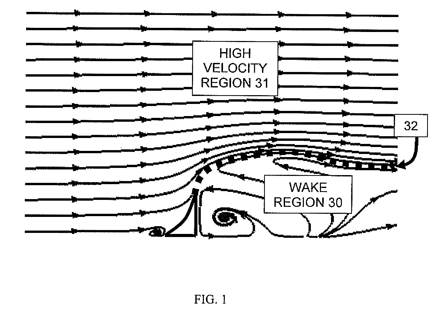
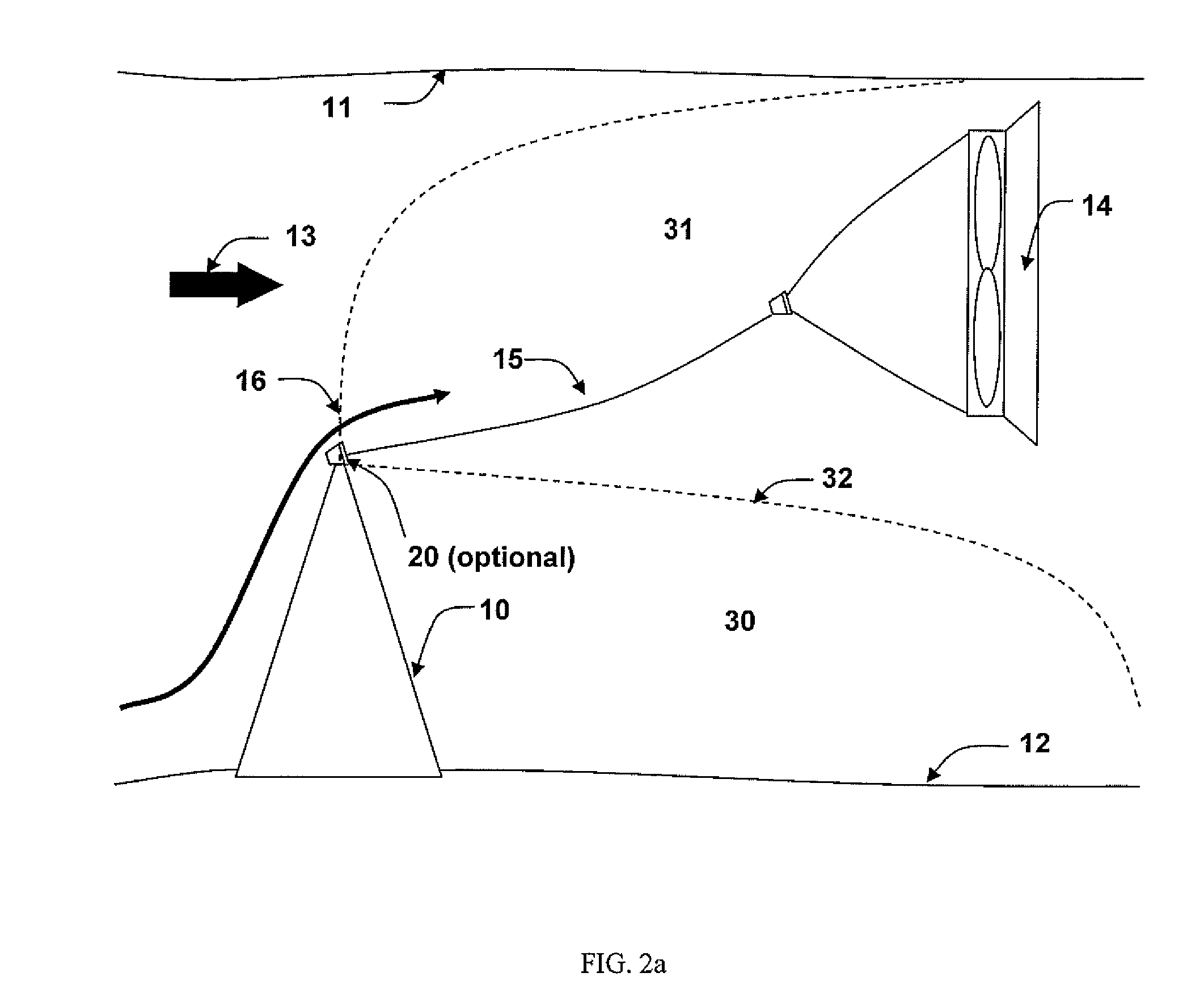
[0008]The disclosed method consists of an object placed on the ocean floor, riverbed or channel bottom upstream of the kinetic hydro turbine. The size and geometry of the object is optimized to disturb the boundary layer to increase the power density seen at the turbine. The object is also selected for its ability to form a large wake region to allow protecting the turbine when needed. Symmetrical shapes offer the added advantage to perform similarly in tidal applications where the flow changes direction periodically.
[0010]More particularly, the disclosed invention consists of placing a boundary layer disturbing object at the bottom of an ocean floor, riverbed and channel bottom to modify the boundary layer. The shape of the boundary layer disturbing object is optimized to provide a velocity increase above and downstream of the shaped object to increase the power density of the kinetic hydro turbine and to provide a wake region behind the shaped object to reduce the flow velocity and thereby avoid damage to the turbine when environmental elements like heavy logs, storms and spring ice breakup risk damaging or destroying the hydro kinetic turbine.
[0018]The method may include shaping said object to have a cross-sectional area perpendicular to the direction of the flow which is plural times greater than a cross-sectional area in the direction of the flow so as to maximize a cross-stream area of said object.
[0028]Preferably the object is shaped to maximize an effect of the object on the boundary layer in the flow of fluid to redirect the boundary layer outward from the boundary surface.

Problems solved by technology

Furthermore, computational fluid dynamic analyses demonstrate that the geometries that increase energy-densities also produce large wake zones.

Method used


Image

  • Efficiency enhancement and protection method for ocean, river and channel kinetic hydro turbines
  • Efficiency enhancement and protection method for ocean, river and channel kinetic hydro turbines
  • Efficiency enhancement and protection method for ocean, river and channel kinetic hydro turbines

Examples


first embodiment

[0060]Turning now to FIG. 4 and Label A, shape object 10 is illustrated in which the object comprises a rectangular block which is positioned in the flow so as to have a greater extent in lateral direction perpendicular to the flow than in the flow direction. The leading and trailing sides are oriented perpendicularly to the flow. While this embodiment has some beneficial effect, other embodiments appear to have greater positive effect.

second embodiment

[0061]FIG. 4 and Label B illustrates shaped object 10 in which both the front leading side and rear trailing side of the object are sloped at a flat incline in profile. In particular the front leading side tapers at an incline outwardly from the boundary surface in the flow direction while meeting the rear trailing side at an outer apex such that the rear trailing side is inclined inwardly towards the boundary surface in the flow direction.

[0062]A further embodiment is shown in FIG. 4 and Label C in which shape object 10 has the geometry of a section of a cylinder so that the laterally spaced apart ends, the rear trailing side, and the bottom side against boundary surface 12 are all generally flat and rectangular, but the front leading side and the top outer side farthest from the boundary surface form a continuous curving surface which is convex in profile so that the leading surface or leading side of shape object 10 again extends outwardly from the boundary surface at an incline ...


PUM


Abstract

Kinetic energy contained in oceans, rivers and channels can be converted to power using kinetic hydro turbines. These turbines can be tethered to the ocean floor, riverbed and channel bottom and their vertical position within the water column controlled. A method is disclosed that permits to increase the power extracted by the turbine by modifying the boundary layer using a shaped object located upstream of the turbine to increase the flow velocity through the turbine. The object also provides protection during climatic events like spring ice breakup, logs and storms that could damage the turbine. Additionally the shaped object can allow the turbine to be tethered to it. The shaped object can be made symmetric to allow operating in tidal conditions where the flow direction changes periodically. On site manufacturing can also alleviate overall costs.

Description

[0001]The present application claims benefit under 35 USC Section 119(e) of U.S. Provisional Patent Application Ser. No. 60 / 971,749, filed on Sep. 12, 2007. The present application is based on and claims priority from this application, the disclosure of which is expressly incorporated herein by reference.FIELD OF THE INVENTION[0002]The present invention relates to an improved energy generation method using kinetic water currents to increase the efficiency of kinetic hydro turbines.BACKGROUND OF THE INVENTION[0003]The following patents are considered to be related to the general field of the present invention: Canadian Patents and / or Applications: 2,556,702; 2,460,479; and 2,868,717 and U.S. Pat. Nos.: 3,986,787; 4,095,918; 4,025,220; 4,163,904; 4,219,303; 4,613,279; 6,139,255; 6,406,251; 6,168,373; 6,531,788; 6,652,221; 7,105,942; and 7,291,936.[0004]Kinetic hydro turbines extract energy from the flow by installing a horizontal or vertical turbine in a fixed position. These turbines...

Claims


Application Information

Patent Timeline
Patent Type & Authority Applications(United States)
IPC IPC(8): F03B11/00F03B3/00
CPCF03B13/264F03B17/061Y02E10/28F05B2240/917F05B2240/93F05B2240/122F05B2240/9176Y02E10/30Y02P70/50Y02E10/20
Inventor BIBEAU, ERIC L.GADEN, DAVID L.F.
Owner BIBEAU ERIC L
Learn More