Layered structure for use with high power light emitting diode systems

a light-emitting diode and layered structure technology, which is applied in the direction of instruments, paper/cardboard containers, lighting support devices, etc., can solve the problems of poor thermal conductivity, insufficient air or air filling of larger voids, and insufficient thermal grease and adhesive thermal tapes

Active Publication Date: 2009-09-10
METROSPEC TECH
View PDF20 Cites 72 Cited by
  • Summary
  • Abstract
  • Description
  • Claims
  • Application Information

AI Technical Summary

Problems solved by technology

FR4 materials are known to be poor thermal solutions for high heat circuits as the electrically insulating layer results in poor thermal conductivity from the LED heat sink slug to the assembly heat sink.
Thermal grease and adhesive thermal tapes fill small voids of 0.002 inch or less due to surface irregularities but are not sufficient to fill larger voids or air gaps commonly occurring between standard circuit board materials and the assembly heat sinks due to the heat sinks being made out of flat, twisted, or curved surfaces.
Issues with poor conductive interfaces quickly lead to failed LED systems in applications in the field due to voids or air gaps between the MCPCB or other substrate and the intended heat sink.
These applications typically suffer from poor transfer of heat from the LED source to the heat sink due to poor conductive surface contact due to the board being too rigid to conform to the heat sink shape or to poor heat transfer through the board due to MCPCB thickness and layered structure properties.
These materials provide better thermal management of high power LEDs over standard circuit board materials due to their higher thermally conductive materials but suffer from the same heat sink interface issues as the standard circuit board material and further at a severe sacrifice to system costs.
The introduction of LED systems into many general illumination and display applications is limited due to the high front end costs of LED systems.
While the performance of the LEDs continue to climb and the cost of the LEDs continues to drop at rates consistent with other semiconductors following Mohr's Law, little is being done to reduce the costs related to the support systems necessary for high power LED systems such as board substrates.
The costs of assembling LED systems into lighting fixtures are further increased due to the labor intensive nature of applying rigid board materials with thermal grease, paste, or adhesive along with mechanical fastening of the rigid board materials to heat sinks.
Flexible tape and reel solutions have been developed for low wattage LED systems, however, these solutions are not applicable to high wattage LED systems due to the amount of heat generated by the higher wattage systems and the inherent poor thermal properties of the flexible materials such as DuPont™ Kapton™ polyimide film.

Method used


Image

  • Layered structure for use with high power light emitting diode systems
  • Layered structure for use with high power light emitting diode systems
  • Layered structure for use with high power light emitting diode systems

Examples


Embodiment Construction

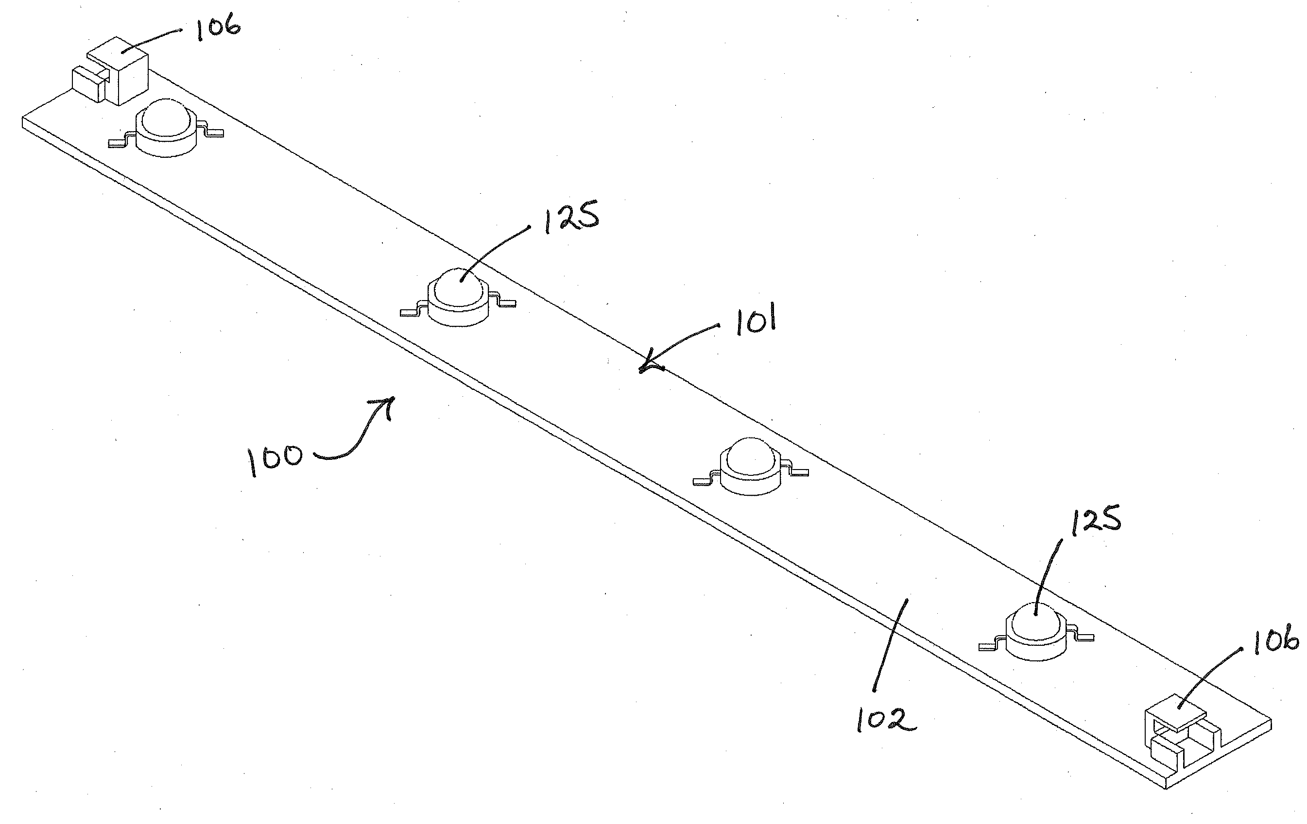
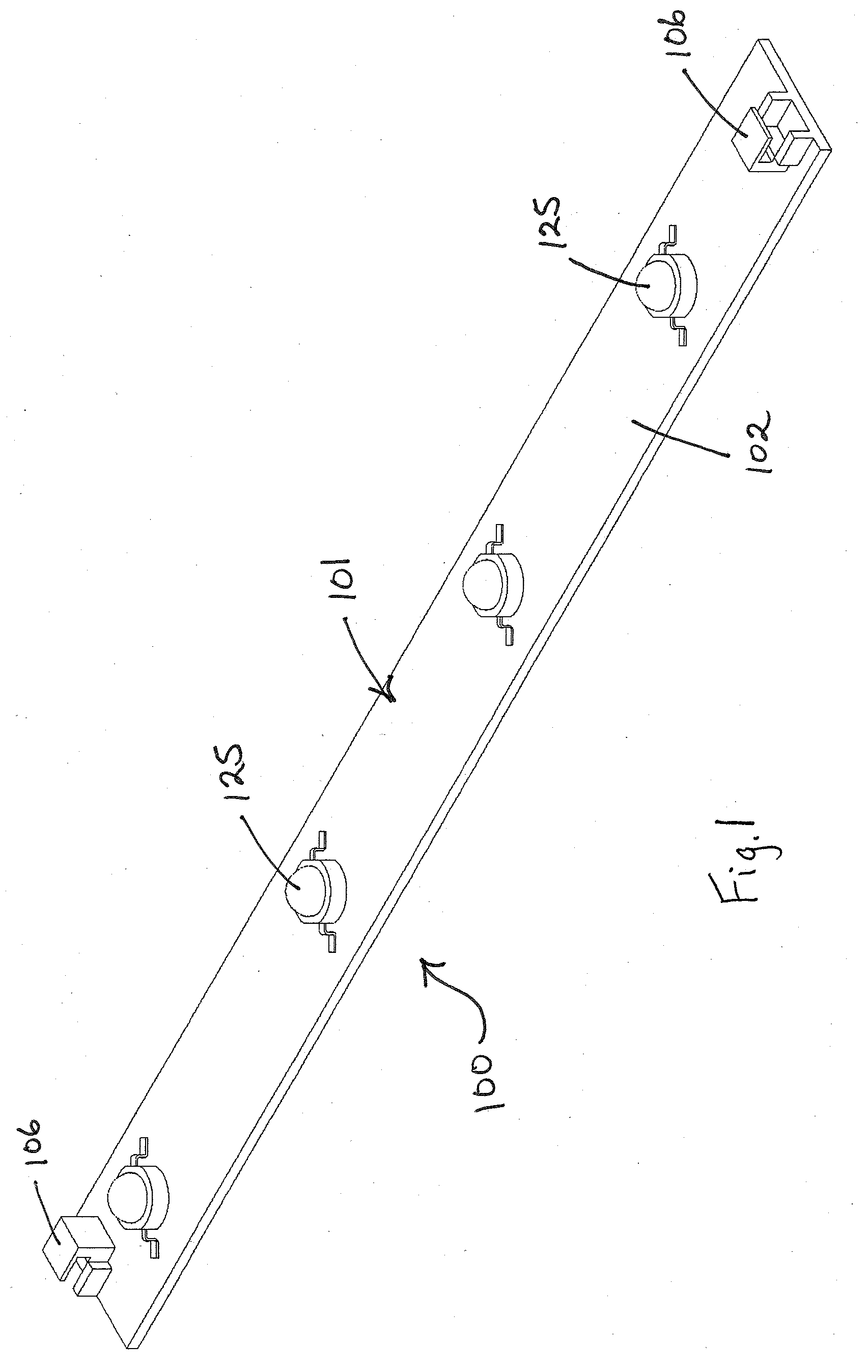
[0028]A preferred embodiment layered structure for use with high power light emitting diode systems constructed according to the principles of the present invention is designated by the numeral 100 in the drawings.

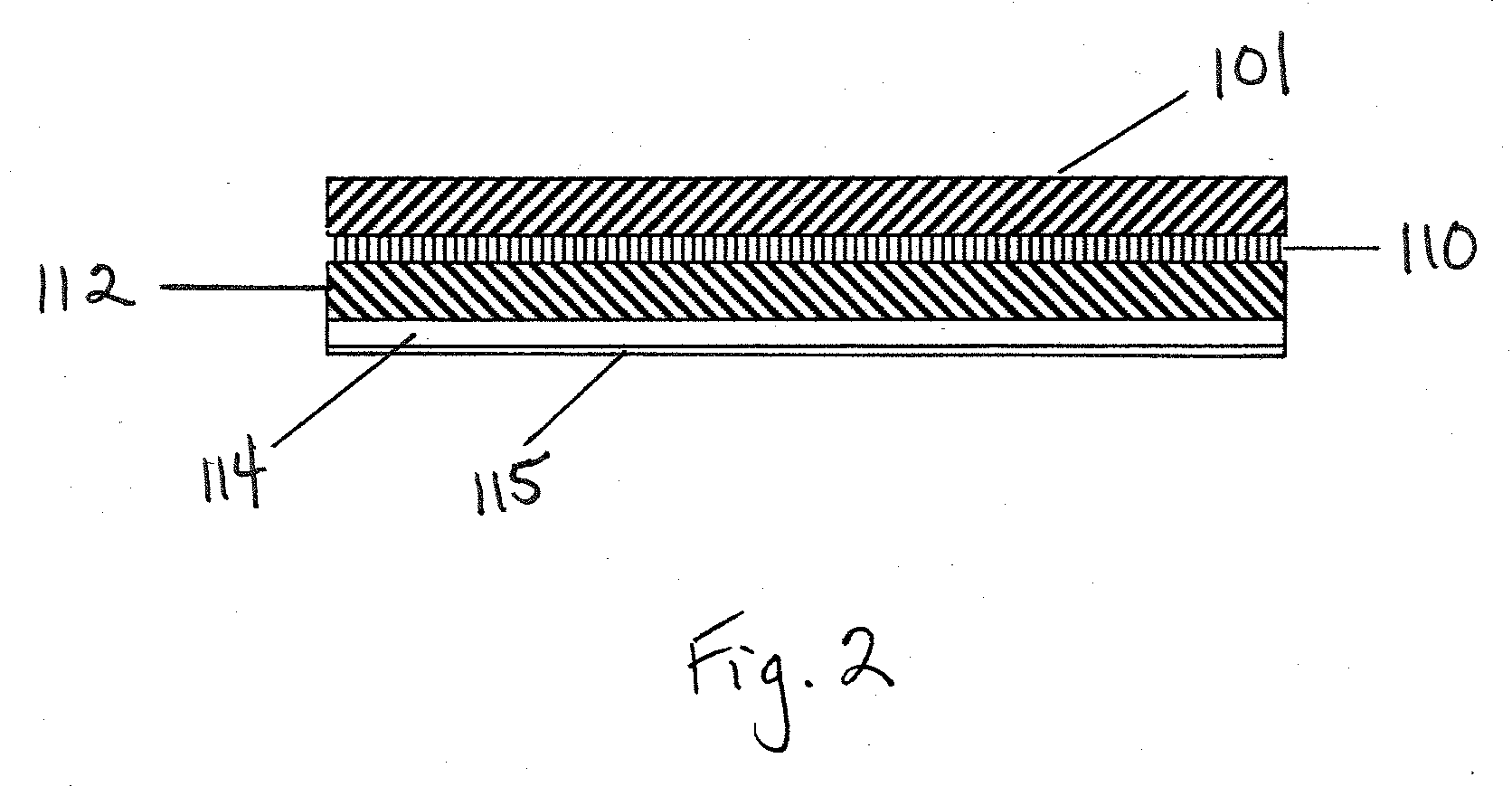
[0029]As shown in FIG. 2, the layered structure 100 generally includes a top layer 101, an intermediate layer 110, and a bottom layer 112. Preferably, a commercially available FR4 material is used as a starting material and is modified to create the layered structure 100. The FR4 material preferably includes a layer of fiberglass sandwiched between two layers of copper. An example of a suitable FR4 material is FR406 manufactured by Isola Group of Chandler, Arizona. The top layer 101 includes one of the two layers of copper, the intermediate layer 110 includes the layer of fiberglass, and the bottom layer 112 includes the other of the two layers of copper. It is recognized that other suitable FR4 materials could be used and that these layers could be either manufactured or ...


PUM

PropertyMeasurementUnit
thickaaaaaaaaaa
flatnessaaaaaaaaaa
flatnessaaaaaaaaaa

Abstract

A layered structure for use with a high power light emitting diode system comprises an electrically insulating intermediate layer interconnecting a top layer and a bottom layer. The top layer, the intermediate layer, and the bottom layer form an at least semi-flexible elongate member having a longitudinal axis and a plurality of positions spaced along the longitudinal axis. The at least semi-flexible elongate member is bendable laterally proximate the plurality of positions spaced along the longitudinal axis to a radius of at least 6 inches, twistable relative to its longitudinal axis up to 10 degrees per inch, and bendable to conform to localized heat sink surface flatness variations having a radius of at least 1 inch. The top layer is pre-populated with electrical components for high wattage, the electrical components including at least one high wattage light emitting diode at least 1.0 Watt per 0.8 inch squared.

Description

FIELD OF THE INVENTION[0001]The present invention relates to a layered structure for use with high power light emitting diode systems.BACKGROUND OF THE INVENTION[0002]Lighting systems utilizing multiple emitters or light emitting diodes (hereinafter “LEDs”) are used in a variety of applications including but not limited to retail displays, refrigeration and freezer door systems, under cabinet lighting, track lighting, and cove lighting. Continuous strings of LEDs are often used in these applications and may be individually wired together or soldered onto printed circuit board substrates. Typical applications use standard circuit board materials such as Flame Retardant 4 (hereinafter “FR4”) or Metal Core Printed Circuit Boards (hereinafter “MCPCBs”), which are typically rigid.[0003]Designers of high power LED systems quickly adopted these standard circuit board materials due to their low cost and wide spread availability. The broadest applications focus on the use of aluminum clad MC...

Claims


Application Information

Patent Timeline
Patent Type & Authority Applications(United States)
IPC IPC(8): B32B33/00B32B37/00
CPCB32B33/00Y10T428/14B32B2307/302B32B2311/12B32B2315/085H05K1/0366H05K1/189H05K3/0061H05K3/0097H05K2201/09018H05K2201/10106H05K2203/1545F21K9/30F21V21/14F21V29/70Y10T428/26Y10T156/10B32B2307/206F21K9/20
Inventor CRANDELL, WM. TODDJOHNSON, ANTHONY MITCHELLSCHWEITZER, TONY STEPHENHOLEC, H. VIC
Owner METROSPEC TECH
Why Eureka
Try Eureka