Control device and control method for vehicle

a control device and control method technology, applied in the direction of electric control, gearing, machines/engines, etc., can solve the problems of reducing the torque desirably, the inability to and the consumption of engine power by increasing the rotational speed of the engine, so as to suppress the increase in the rotational speed reduce the torque of the second electric motor. , the effect of reducing the differen

Inactive Publication Date: 2009-09-10
TOYOTA JIDOSHA KK
View PDF20 Cites 66 Cited by
  • Summary
  • Abstract
  • Description
  • Claims
  • Application Information

AI Technical Summary

Benefits of technology

[0034]In the fourth aspect of the invention, the amount of electric power generated by (the power generation amount of) the first electric motor that controls the rotational speed of the engine is taken into consideration, and the output of the engine is restricted so that electric power balance is constantly maintained between the first electric motor and the second electric motor during downshifting. Specifically, the output of the engine is restricted so that, during downshifting, the power generation amount (which may include the amount of power consumed by auxiliary machines (auxiliary machine consuming amount), which will be described later) of the first electric motor falls within the electric power acceptance limit of the electric storage device. With the above output restriction control, it is possible to reduce the torque of the second electric motor during downshifting and, therefore, it is possible to suppress an increase in rotational speed of the second electric motor. By so doing, it is possible to reduce a difference between the rotational speed of the second electric motor and the engaging target rotational speed (synchronous rotational speed of a target gear) when the frictional engagement element is engaged. Thus, shift shock may be suppressed, and the friction material of the frictional engagement element may be protected.

Problems solved by technology

However, when the engine operates at a high rotational speed, a protection control (engine overrun prevention control) is activated and, as a result, torque of the second electric motor cannot be reduced.
That is, when the engine rotational speed is low, an engine power may be consumed by increasing the engine rotational speed.
As the amount of electric power generated by the first electric motor increases in this way, the second electric motor (motor) is required to consume electric power and, therefore, cannot reduce the torque desirably.
Then, when the torque of the second electric motor cannot be reduced during downshifting because of the above reason, an increase in rotational speed of the second electric motor, which is associated with gear shifting, cannot be restricted.
This may produce engagement shock.
In addition, a thermal load on the friction material of the frictional engagement element may increase.
However, to ensure the capacity that allows charging of electric power in any conditions, including charging of the amount of electric power generated by the first electric motor when the engine is rotated at a high speed, or the like, the specification of the battery becomes excessive and, therefore, it is difficult to implement such a battery.
In addition, in a hybrid vehicle, techniques for canceling variations in driving force during shifting by a cooperative control between a motor (generator) and an engine are disclosed; however, even with these techniques, the cooperative control may not be executed during shifting because of components protection control, or the like.
Thus, shift shock may occur and a thermal load on the friction material may increase.

Method used


Image

  • Control device and control method for vehicle
  • Control device and control method for vehicle
  • Control device and control method for vehicle

Examples


Embodiment Construction

[0054]Hereinafter, an embodiment of the invention will be described with reference to the accompanying drawings.

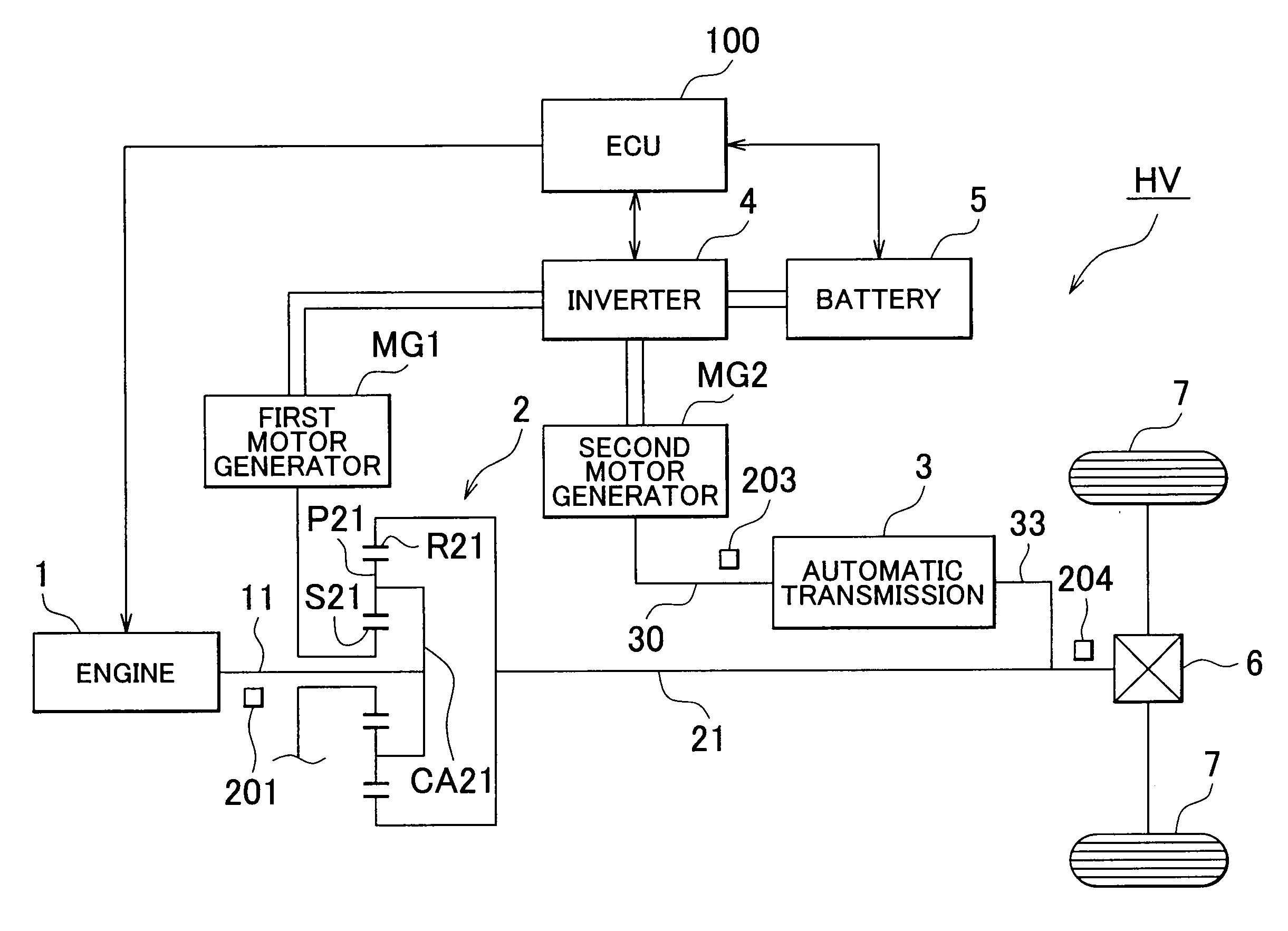
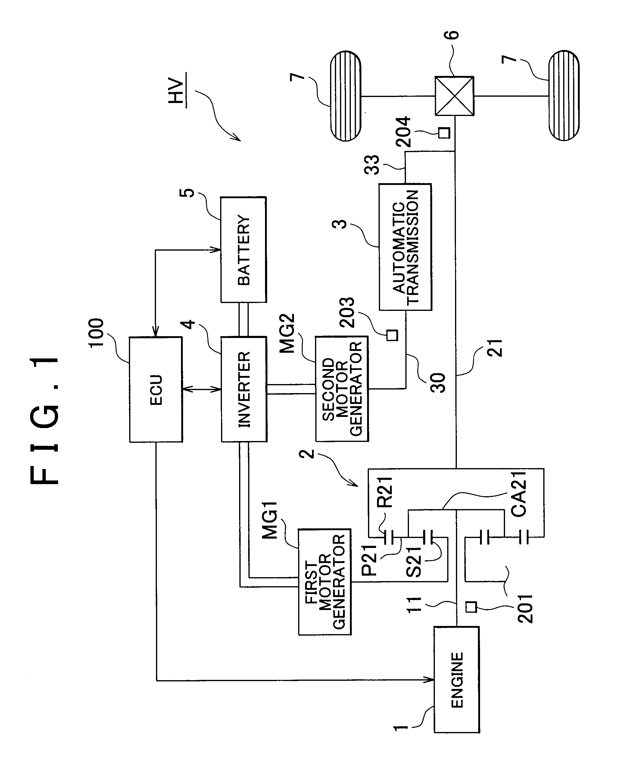
[0055]FIG. 1 is a schematic configuration diagram that shows an example of a hybrid vehicle according to the embodiment of the invention.

[0056]A hybrid vehicle HV in this embodiment includes an engine 1, a first motor generator MG1, a second motor generator MG2, a power distribution mechanism 2, an automatic transmission 3, an inverter 4, a battery (HV battery) 5, a differential gear 6, driving wheels 7, a hydraulic pressure control circuit 300 (see FIG. 4), a shift operating device 8 (see FIG. 5A and FIG. 5B), an electronic control unit (ECU) 100, and the like.

[0057]These engine 1, motor generators MG1 and MG2, power distribution mechanism 2, automatic transmission 3 (including the hydraulic pressure control circuit 300), shift operating device 8 and various components of the ECU 100 will be described below.

[0058]The engine 1 is a known power source, such as a gasoline en...


PUM


Abstract

During downshifting, a control for restricting an output of an engine to constantly maintain electric power balance between a first electric motor and a second electric motor or a control for suppressing a rate of increase in engine rotational speed by a control on the engine, such as ignition timing retardation control or fuel injection amount reduction control, is executed to thereby allow torque of the second electric motor to be reduced during downshifting. In addition, the engine rotational speed is decreased before downshifting, and, after the engine rotational speed is decreased to a rotational speed at which a protection control is not activated, an automatic transmission downshifts. With the above control, it is possible to suppress an increase in rotational speed of the second electric motor during downshifting. Thus, shift shock may be suppressed, and the friction material of the frictional engagement element may be protected.

Description

INCORPORATION BY REFERENCE[0001]The disclosure of Japanese Patent Application No. 2008-053374 filed on Mar. 4, 2008 including the specification, drawings and abstract is incorporated herein by reference in its entirety.BACKGROUND OF THE INVENTION[0002]1. Field of the Invention[0003]The invention relates to a control device and control method for a vehicle equipped with a differential unit that outputs at least portion of power from an engine to driving wheels; a first electric motor coupled to a rotating element of the differential unit; and a second electric motor, wherein power from the second electric motor is output through a step-gear automatic transmission to the driving wheels.[0004]2. Description of the Related Art[0005]In recent years, in terms of environmental protection, it is desired to reduce exhaust gas emissions from an engine (internal combustion engine) mounted on a vehicle and to improve a specific fuel consumption (fuel economy), and a hybrid vehicle equipped with...

Claims


Application Information

Patent Timeline
Patent Type & Authority Applications(United States)
IPC IPC(8): B60W10/04B60K1/02B60K6/28B60K6/445B60K6/547B60L50/16B60W10/06B60W10/10B60W10/11B60W10/115B60W20/00F02D29/00F02D29/02F02D41/04F16H59/14F16H59/42F16H59/44F16H61/04F16H61/68F16H61/684F16H61/686F16H63/50
CPCB60K6/445Y10T477/23B60L2240/421B60W10/06B60W10/08B60W10/115B60W20/00B60W30/19B60W2710/0616B60W2710/0644B60W2710/081F16H2037/0873Y02T10/6286Y02T10/642Y02T10/6239B60K6/547Y02T10/62Y02T10/64B60W20/10
Inventor ITO, MASATOSHIUEJIMA, TAIYO
Owner TOYOTA JIDOSHA KK
Why Eureka
Try Eureka