Diagnostics for two-mode variable valve activation devices

a technology of activation device and valve, which is applied in the direction of machines/engines, output power, process and machine control, etc., can solve problems such as the compression load of piezo-electric transmitters

Active Publication Date: 2009-09-10
DELPHI TECH IP LTD
View PDF3 Cites 63 Cited by
  • Summary
  • Abstract
  • Description
  • Claims
  • Application Information

AI Technical Summary

Benefits of technology

[0011]Briefly described, the invention addresses the shortcomings of prior art diagnostic strategies and algorithms for a low-lift or zero-lift failure mode of two-mode Variable Valve Activation (VVA) lost motion devices by integrating a piezo-electric Radio Frequency (RF) transmitter in each individual two-mode VVA device of a multiple-cylinder internal combustion engine. The direct measurement of the mode of each two-mode VVA device as opposed to the prior art attempts to infer the proper function of these devices by applying arcane neutral net or fuzzy logic data analysis techniques to existing engine control system data, is both more reliable and more efficient in it's use of engine controller resources, such as Random Access Memory (RAM), Read-only Memory (ROM), and throughput. The diagnostics in accordance with the invention is applicable for a variety of two-mode VVA lost motion devices, for example two-step and deactivation RFFs with compression or torsion lost motion springs, deactivation roller hydraulic valve lifters with internal or external lost motion springs, and deactivation switching Hydraulic Lash Adjusters (HLA).

Problems solved by technology

This cyclical load on the spring results in a compression load upon the piezo-electric transmitter.

Method used


Image

  • Diagnostics for two-mode variable valve activation devices
  • Diagnostics for two-mode variable valve activation devices
  • Diagnostics for two-mode variable valve activation devices

Examples


Embodiment Construction

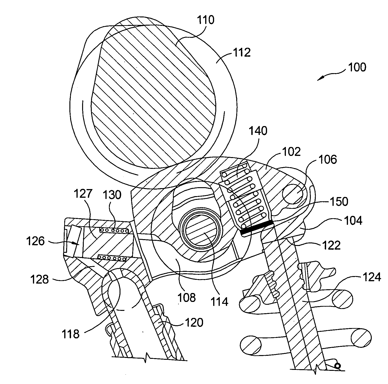
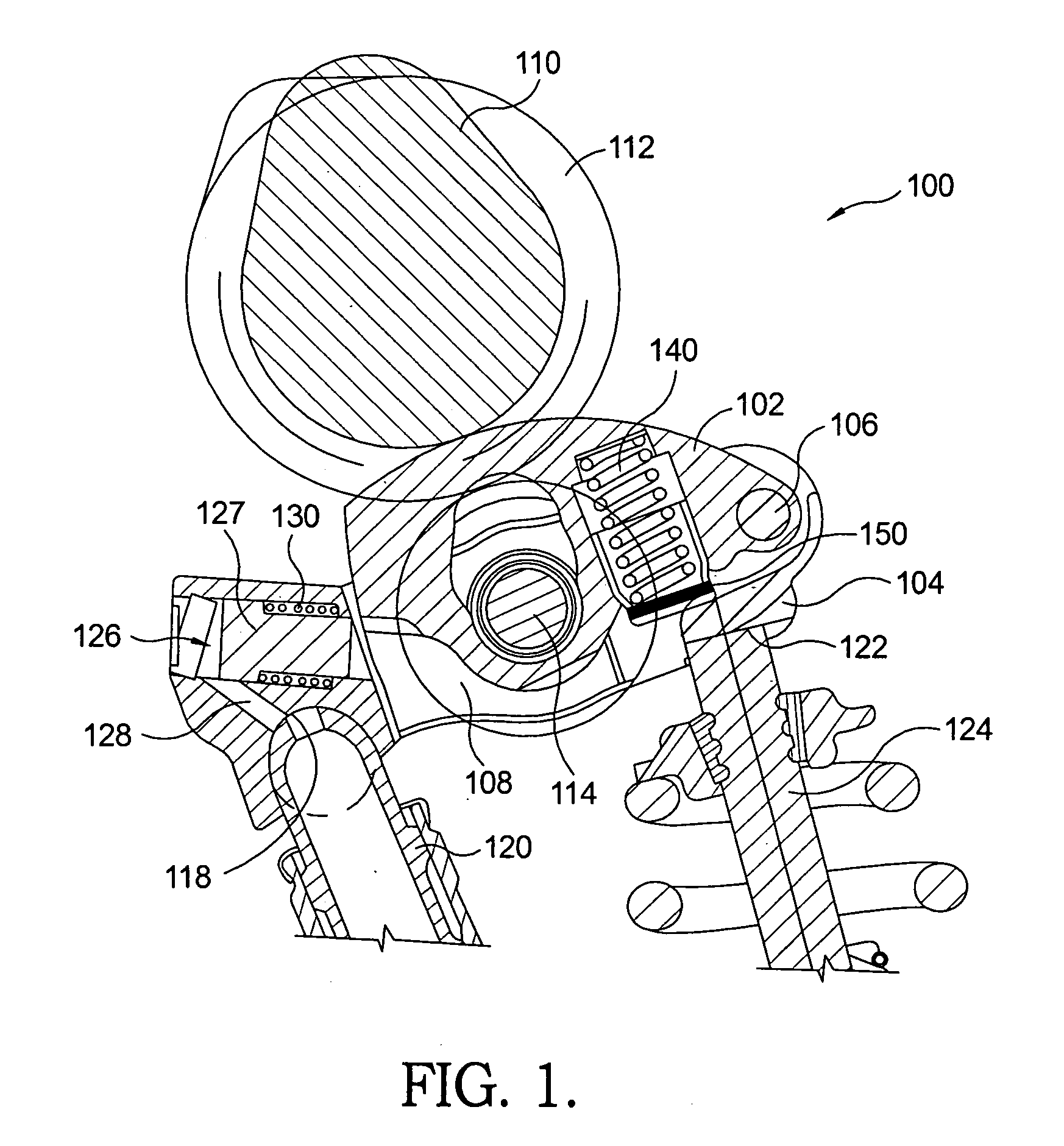
[0023]Referring to FIG. 1, a two-step Roller Finger Follower (RFF) assembly 100 includes an inner arm 102 that is pivotably disposed in an outer arm 104. Inner arm 102 pivots within outer arm 104 about a pivot shaft 106. A roller 108 for following a cam lobe 110 of a lifting cam of an engine camshaft 112 is carried by a shaft 114 that is supported by outer arm 102. A socket 118 for pivotably mounting RFF assembly 100 on a Hydraulic Lash Adjuster (HLA) 120 is included at one end of outer arm 104. A pad 122 for actuating a valve stem 124 is included at an opposite end of outer arm 104. A latching mechanism 126, such as lock pin 127, disposed within outer arm 104 at the same end as socket 118 selectively couples or decouples inner arm 102 to or from outer arm 104, which enables switching from a high-lift mode to a low-lift mode and vice versa. Controlled by an engine control module, pressurized oil supplied by the HLA 120 through oil passage 128 in known fashion hydraulically biases lo...


PUM


Abstract

A method for detecting a low-lift or zero-lift failure mode in a variable valve activation system of an internal combustion engine includes the steps of positioning a piezo-electric element that acts as a radio frequency transmitter relative to a lost motion spring of a two-mode variable valve activation lost motion device, subjecting the piezo-electric element to a compression load when a load from displacement of a lobe of a camshaft acts on the lost motion spring, broadcasting a radio frequency signal each time the piezo-electric element is subjected to the compression load, and evaluating the presence or absence of the broadcasted radio frequency signal in relation to an expected presence or absence of the radio frequency signal. The direct measurement of the mode of each two-mode device is both more reliable and more efficient in the use of engine controller resources compared to currently existing diagnostic methods.

Description

TECHNICAL FIELD[0001]The present invention relates to mechanisms for altering the actuation of valves in internal combustion engines; more particularly, to two-mode variable valve activation devices; and most particularly, to a method and apparatus for detection of a low-lift or zero-lift failure mode for such devices.BACKGROUND OF THE INVENTION[0002]Variable Valve Activation (VVA) mechanisms for internal combustion engines are well known. It is known to lower the lift, or even to provide no lift at all, of one or more valves of a multiple-cylinder engine, during periods of light engine load. Such deactivation or valve lift switching can substantially improve fuel efficiency.[0003]Various approaches are known for changing the lift of valves in a running engine. One known approach is to provide an intermediary cam follower arrangement, which is rotatable about the engine camshaft and is capable of changing the valve lift and timing, the camshaft typically having both high-lift and lo...

Claims


Application Information

Patent Timeline
Patent Type & Authority Applications(United States)
IPC IPC(8): G01M15/04F01L1/34F02D13/00
CPCF01L1/08F01L1/185F01L1/2405F01L1/2422F01L13/0005F01L13/0021Y02T10/18F01L2800/00F01L2800/12F01L2820/04F02D13/06F02D41/221G01M15/042F01L2105/00F01L2305/00Y02T10/12
Inventor WATERS, JAMES P.GUTTERMAN, JEFFREY S.
Owner DELPHI TECH IP LTD
Why Eureka
Try Eureka