Sensor-Incorporated Wheel Support Bearing Assembly

US20090229379A1Inactive Publication Date: 2009-09-17NTN CORP

Image

  • Sensor-Incorporated Wheel Support Bearing Assembly
  • Sensor-Incorporated Wheel Support Bearing Assembly
  • Sensor-Incorporated Wheel Support Bearing Assembly

Examples


Embodiment Construction

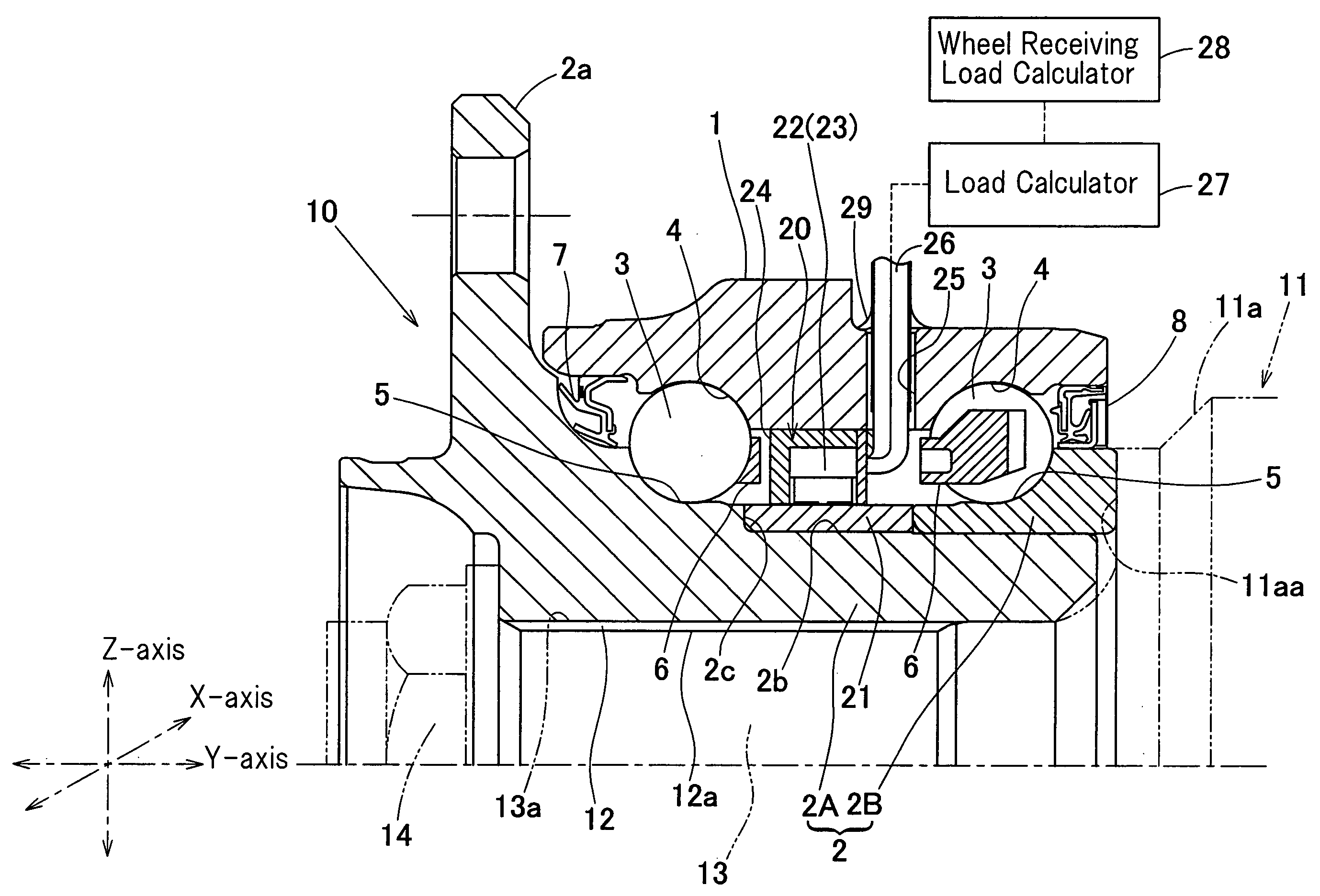
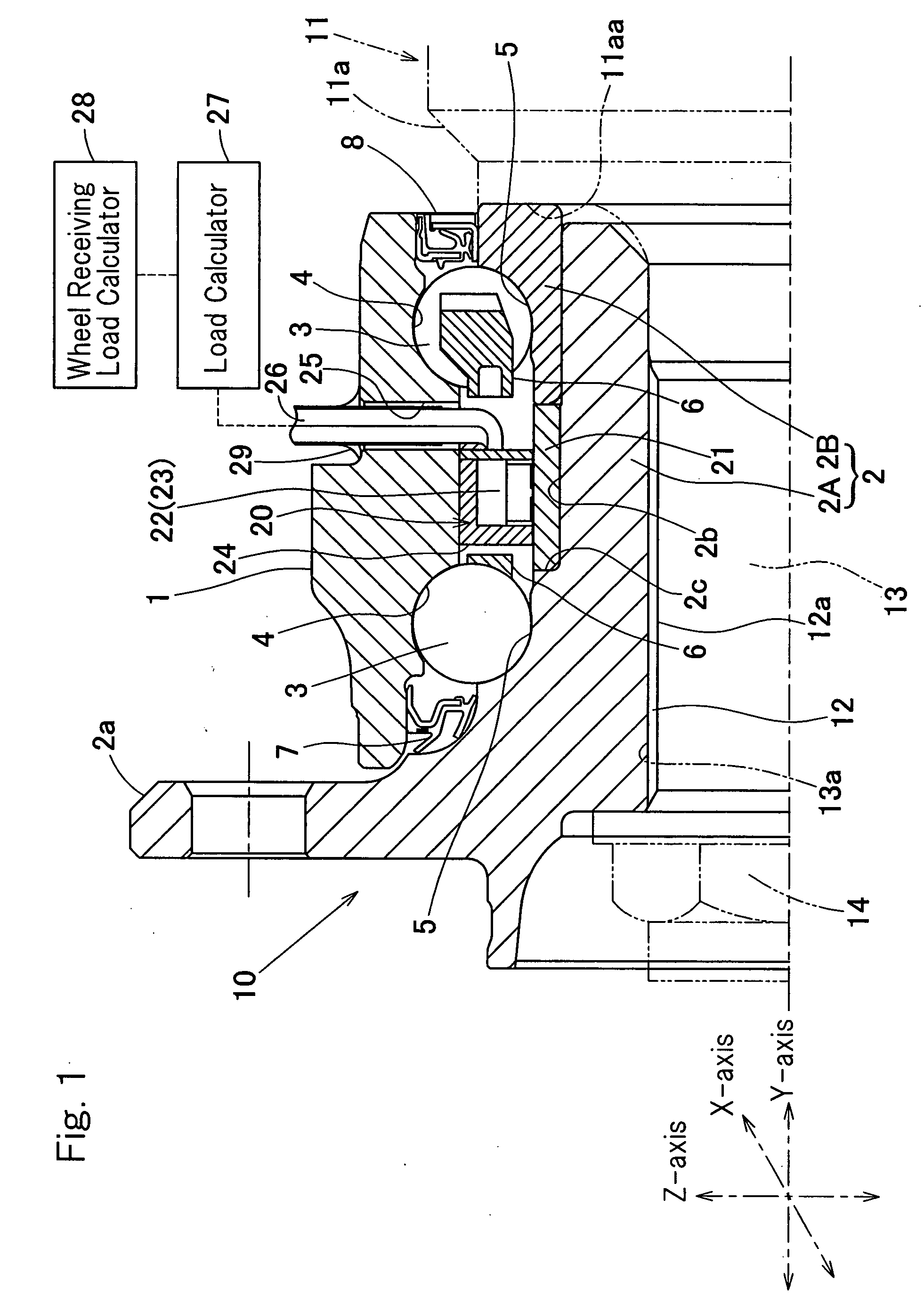
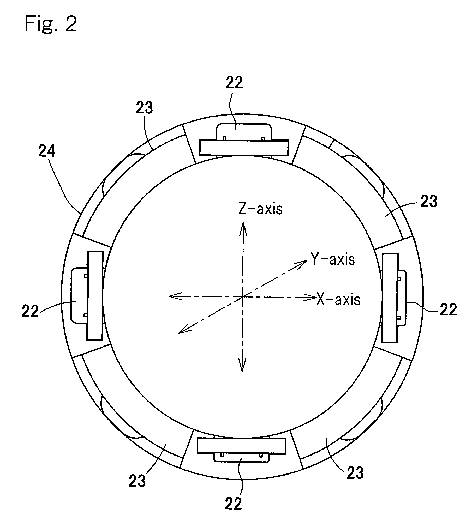
[0027]A preferred embodiment of the present invention will now be described with particular reference to FIGS. 1 to 3. This embodiment is directed to a third-generation wheel support bearing assembly of an inner-race rotating type that is used for the support of a vehicle drive wheel. It is to be noted that in the specification herein set forth, the terms ā€œoutboardā€ and ā€œinboardā€ represent one side of the vehicle body away from the longitudinal center of the vehicle body and the other side of the vehicle body close to the longitudinal center of the vehicle body, respectively. In FIG. 1, a right portion represents the inboard side whereas a left portion represents the outboard side.

[0028]The wheel support bearing assembly 10 shown in FIG. 1 has a horizontally extending longitudinal axis and includes an outer member 1 having an inner peripheral surface formed with a plurality of, for example, double rows of raceway surfaces 4, an inner member 2 having an outer peripheral surface forme...


PUM


Abstract

A wheel support bearing assembly includes an outer member (1) having an inner peripheral surface formed with raceway surfaces (4), an inner member (2) having an outer peripheral surface formed with raceway surfaces (5) in face-to-face relation with the raceway surfaces (4) in the outer member (1), and rows of rolling elements (3) interposed between the raceway surfaces (4, 5). A ring member (21) made of a magnetostrictive material is fixed to the outer peripheral surface of the inner member (2), and a magnetostrictive sensor (23) and a displacement sensor (22) are disposed in the outer member (1) or a member (24) fixed to the outer member (1) to confront the ring member. The magnetostrictive sensor (23) measures a change in magnetic strain occurring in the ring member (21) and the displacement sensor (22) measures the distance between the ring member (21) and the displacement sensor (22).

Description

BACKGROUND OF THE INVENTION[0001]1. Field of the Invention[0002]The present invention relates to a sensor-incorporated bearing assembly equipped with a load sensor for detecting a load imposed on a bearing portion of a wheel.[0003]2. Description of the Prior Art[0004]For safety travel of an automotive vehicle, the wheel support bearing assembly equipped with a sensor for detecting the rotational speed of one of automotive wheels has hitherto been well known in the art. While the automobile traveling safety precaution is hitherto generally taken by detecting the rotational speed of a wheel of various parts, but it is not sufficient with the detection of only the rotational speed of the wheel and, therefore, it is required to achieve an improved safety control with the use of other sensor signals.[0005]In view of this, it may be contemplated to achieve an attitude control of an automotive vehicle based on a load acting on each of wheels during travel of the automotive vehicle. By way ...

Claims


Application Information

Patent Timeline
17 Sep 2009
Publication
US20090229379A1
IPC
G01L1/12
CPC
B60B27/0005; B60B27/0068; G01L5/0023; F16C19/186; F16C19/522; B60B27/0094; F16C2326/02
Inventors
OZAKI, TAKAYOSHI; KOIKE, TAKASHI