High-voltage power unit and mass spectrometer using the power unit

a power unit and power technology, applied in the direction of particle separator tube details, dispersed particle separation, separation process, etc., can solve the problems of elongating the non-detection period, spiking discharge may occur to break the relay, and affecting the accuracy of mass spectrometers, etc., to achieve high reliability, reduce costs, and avoid spiking. the effect of the relay

Active Publication Date: 2009-09-17
SHIMADZU CORP
View PDF5 Cites 38 Cited by
  • Summary
  • Abstract
  • Description
  • Claims
  • Application Information

AI Technical Summary

Benefits of technology

[0017]In a high-voltage power unit according to the preset invention, in order to switch the positive and negative high voltages, there is no need for using high-voltage reed relays or semiconductor switches as in a conventional manner; only a high-voltage-resistance resistor is added and connected in parallel on the output side of each voltage generating circuits. Therefore, a significant cost reduction can be achieved. In addition, a discharge accompanying the switching does not occur, and the breakage of an element thereby does not take place. Even in the case where a spike noise or the like are included in the high-voltage output for some reason, a breakage does not easily occur, unlike a semiconductor switch or the like. Accordingly, a high reliability can be assured for a long period of time.
[0018]In the high-voltage power unit according to the present invention, the controller controls the positive voltage generating circuit and the negative voltage generating circuit, when switching the polarity of the high-voltage output between positive and negative, so that when an output voltage of either one of the voltage generating circuits changes from a first predetermined voltage to zero, an output voltage of the other voltage generating circuit simultaneously changes from zero to a second predetermined voltage.
[0019]That is, there is no need to decrease th

Problems solved by technology

In a high-voltage power unit with such a configuration, when changing a relay, spike discharges may occur to break the relay.
Consequently, it takes some time to change the polarity, which elongates the non-detection period.
In addition, a high-voltage relay of 10 kV or above is generally expensive but nonetheless does not have a very long life time.
That is, it is costly and also has a problem in reliabilit

Method used


Image

  • High-voltage power unit and mass spectrometer using the power unit
  • High-voltage power unit and mass spectrometer using the power unit
  • High-voltage power unit and mass spectrometer using the power unit

Examples


Embodiment Construction

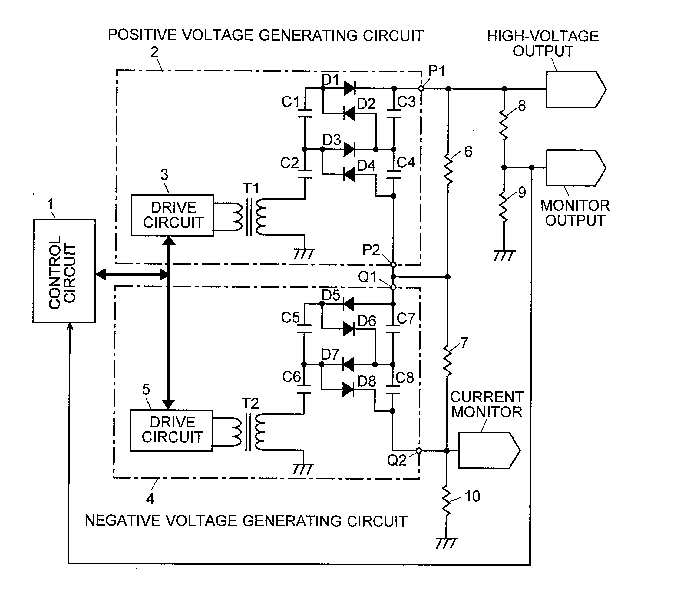
[0029]Hereinafter, one embodiment of a high-voltage power unit according to the present embodiment will be described in detail in reference to FIGS. 1 through 4. FIG. 1 is a configuration diagram of the main portion of the high-voltage power unit according to the present embodiment.

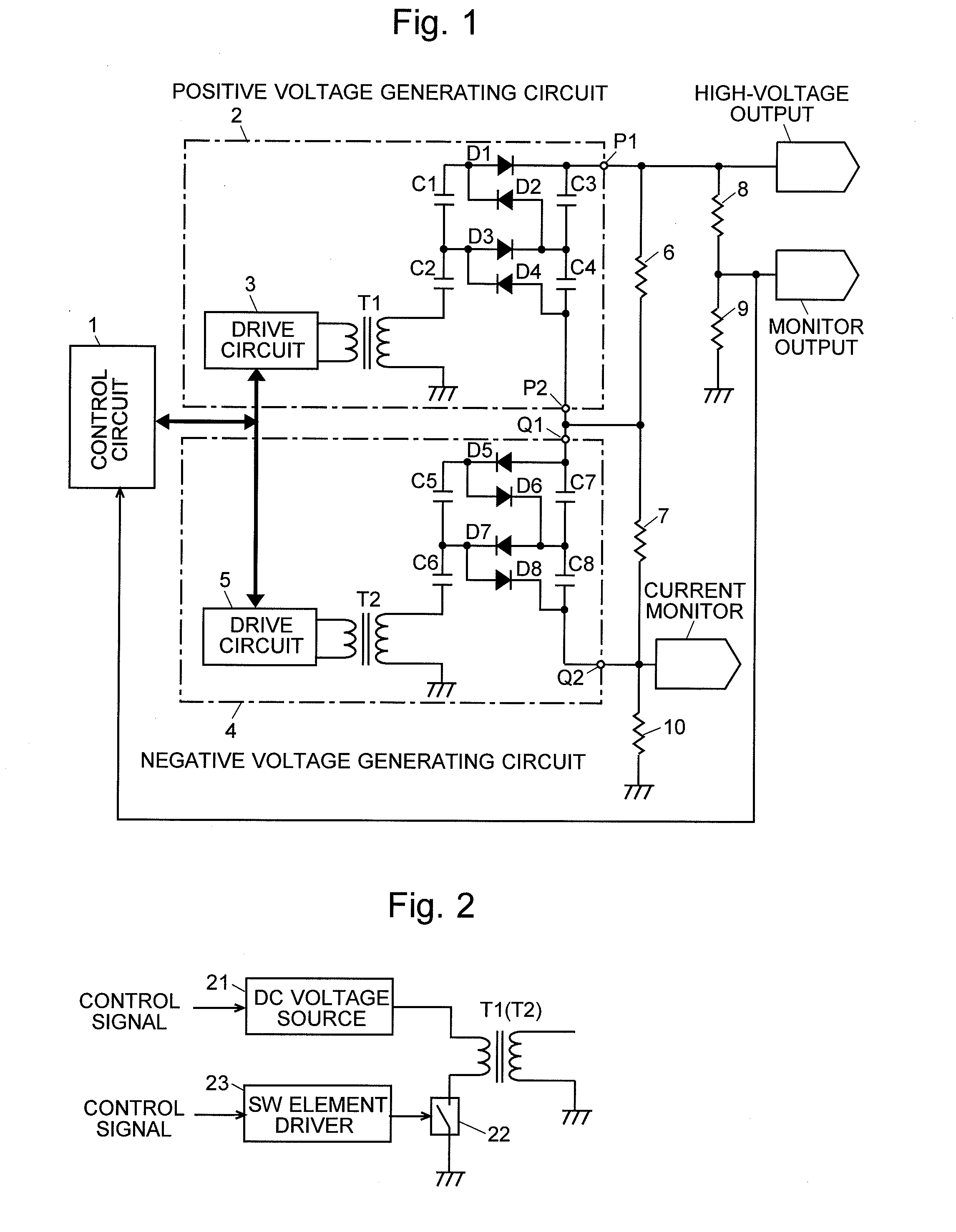
[0030]This high-voltage power unit provides a positive or negative DC high voltage of approximately a few to 10 kV and includes a positive voltage generating circuit 2, a negative voltage generating circuit 4, and a control circuit 1 for controlling the drive circuits 3 and 5 included in the voltage generating circuits 2 and 4. The positive voltage generating circuit 2 and the negative voltage generating circuit 4 basically have the same configuration. For example, the positive voltage generating circuit 2 includes a transformer T1 as a booster, a drive circuit 3 for driving the primary winding of the transformer T1, and a rectifier circuit (voltage quadrupler rectifier circuit) using a Cockcroft-Walton c...


PUM


Abstract

The output terminal P2 of the positive voltage generating circuit 2 and the output terminal Q1 of the negative voltage generating circuit 4 are connected in series. The output terminal Q2 of the negative voltage generating circuit 4 is connected to the ground via the resistor 10. Each of the resistors 6 and 7 is respectively connected in parallel to the voltage generating circuits 2 and 4. A high voltage whose polarity is changed is taken from the output terminal P1 of the positive voltage generating circuit 2. For changing the output voltage from positive to negative one, the control circuit 1 controls each of the drive circuits 3 and 5 so that the output of the positive voltage generating circuit 2 changes from the voltage +HV to zero and the output of the negative voltage generating circuit 4 simultaneously changes from zero to −HV. Accordingly, the output voltage changes in a short period of time. Although a high-voltage-resistance resistor is required in this configuration, it is far more inexpensive and has higher reliability compared to a high-voltage relay or a semiconductor switch which has been conventionally used.

Description

TECHNICAL FIELD[0001]The present invention relates to a high-voltage power unit capable of switching the polarity of an output voltage between positive and negative, and to a mass spectrometer using such a power unit.BACKGROUND ART[0002]Conventionally, ion detectors including a conversion dynode and a secondary-electron multiplier have been used for detecting ions with high sensitivity in a mass spectrometer. In such an ion detector, a high voltage (up to approximately ±10 kV for example) having a polarity opposite to that of the ions to be analyzed is required to be applied to a conversion dynode for selectively detecting positive ions and negative ions. In a liquid chromatograph mass spectrometer, an ion source provided by an electrospray ionization (ESI) method is used for example for vaporizing and simultaneously ionizing a liquid sample. In such an ion source, a high voltage (approximately ±several kV for example) with a polarity equal to that of the ions to be analyzed is requ...

Claims


Application Information

Patent Timeline
IPC IPC(8): H01J49/00H02J1/00
CPCH01J49/022H02M7/103H02M7/10
Inventor MIZUTANI, SHIRO
Owner SHIMADZU CORP
Why Eureka
Try Eureka