
Drying apparatus and drying method for honeycomb formed body

a technology of drying apparatus and honeycomb, which is applied in lighting and heating apparatus, electric/magnetic/electromagnetic heating, furniture, etc., can solve the problems of uneven drying speed of the whole honeycomb formed body, cracks in drying, and problems that tend to occur

Active Publication Date: 2011-10-06
NGK INSULATORS LTD
View PDF11 Cites 10 Cited by
  • Summary
  • Abstract
  • Description
  • Claims
  • Application Information

AI Technical Summary

Benefits of technology

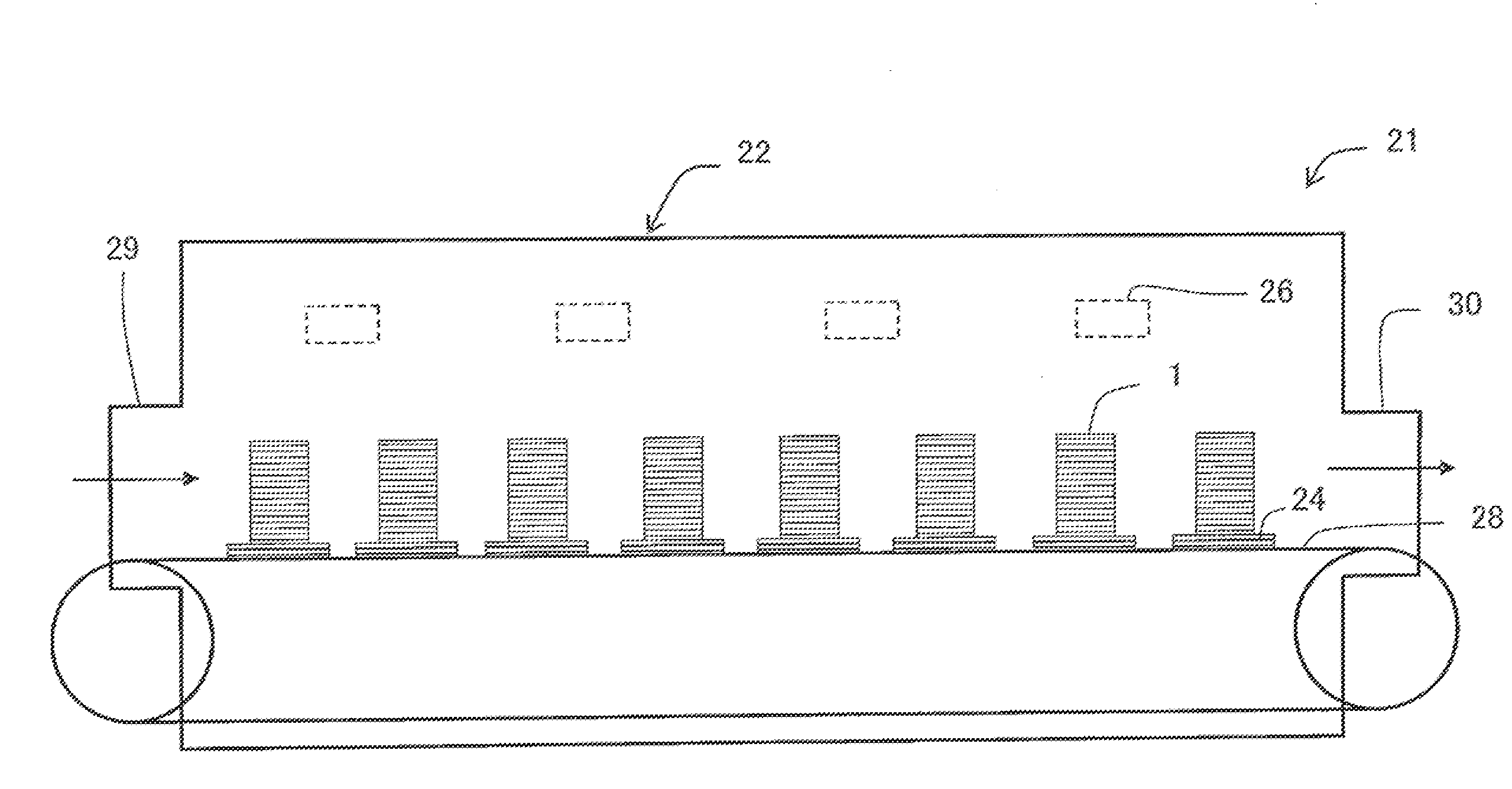
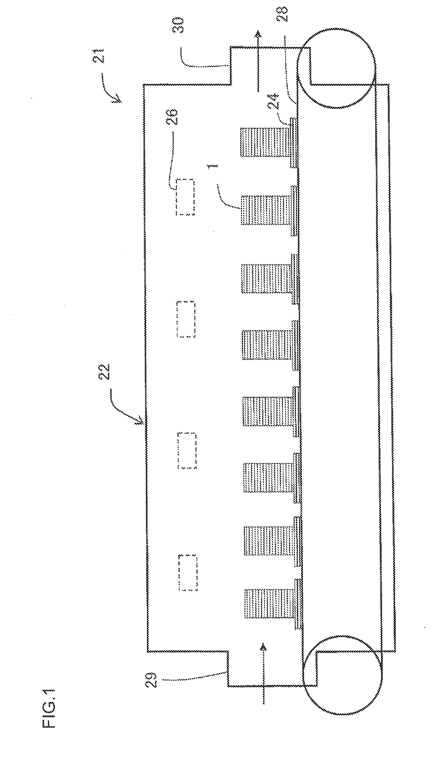
[0010]An object of the present invention is to provide a drying apparatus and a drying method for a honeycomb formed body with which the whole honeycomb formed body can be dried at a uniform speed, and with which drying cracks do not easily occur.
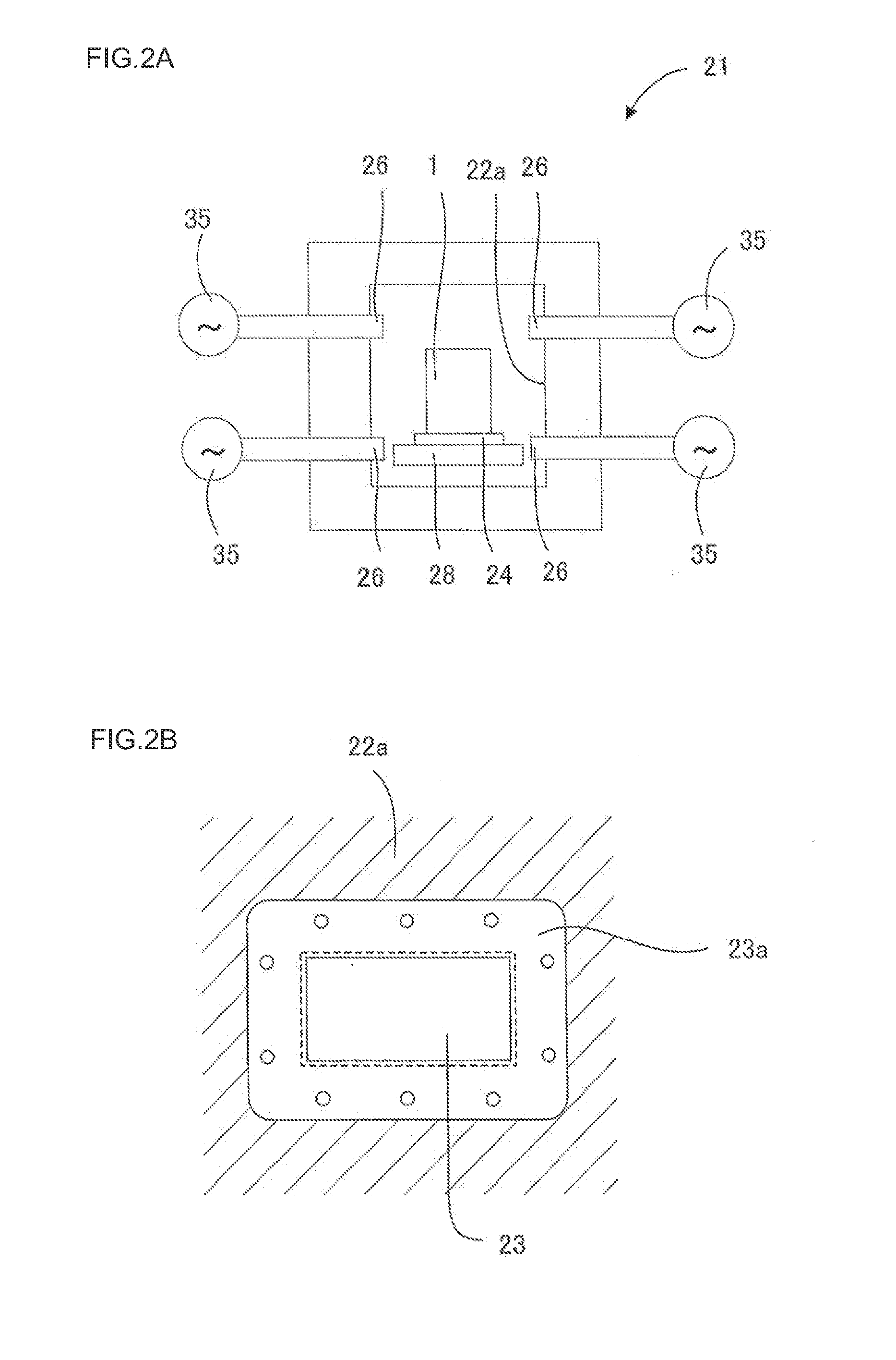
[0012]Since the irradiation ports of the waveguides are provided directed to two or more different directions toward the drying space of the drying chamber, it becomes possible to uniformly dry the honeycomb formed body, thus enabling to prevent drying cracks and cell deformation and to stabilize a shape thereof.

Problems solved by technology

However, when the honeycomb formed body is dried with the microwave drying method, it is difficult to dry the whole honeycomb formed body at a uniform speed.
Moreover, when the honeycomb formed body is dried with the microwave drying method, drying cracks may occur therein.
These problems tend to occur particularly in cases where the honeycomb formed body is the one with a high water content ratio before dried, with a large size, with thick partition walls (with large thickness), with a small opening area of an end surface, formed of a material with large dielectric loss, etc.
Although rotation of the honeycomb formed body is effective to uniformly irradiate microwaves thereto, a rotation mechanism causes the drying apparatus to be complicated and expensive.
In the continuous microwave drying apparatus, it is aimed to average microwave electric field having strength and weakness in a longitudinal direction of the furnace by moving the honeycomb formed body in a traveling direction, and as a result of it, to uniformly irradiate the honeycomb formed body with microwaves, but actually, microwave irradiation becomes non-uniform in some cases.
Although arrangement of irradiation ports and reflecting plates is devised or a stirrer fan etc. are used in the prior art documents, it is not easy to achieve uniformization.
If size of a furnace body is made larger, better uniformization can be achieved, but there is a limit to it.

Method used


Image

  • Drying apparatus and drying method for honeycomb formed body
  • Drying apparatus and drying method for honeycomb formed body
  • Drying apparatus and drying method for honeycomb formed body

Examples


examples 13 to 16

[0084]Next, microwave drying was performed under a condition where a percentage of the upstream and downstream directed waveguides was changed when the percentage of parallelly directed ones was set to be 50%. The results are shown in Table 3. It is to be noted that a water amount difference in Table 3 indicates a water amount difference between a front surface side and a rear surface side of the honeycomb formed body 1 in the conveying direction thereof as shown in FIG. 11.

TABLE 3Percentage ofThe number ofThe number ofPercentage ofCorrespondingparallelupstreamdownstreamupstreamWater amountThe number ofdrawingdirectionsdirectionsdirectionsdirectionsdifferencecracksExample 3FIG. 3C50%101050%0%0 / 10 piecesExample 13—50%61430%8%3 / 10 piecesExample 14FIG. 10A50%81240%3%0 / 10 piecesExample 15FIG. 10B50%12860%−3% 0 / 10 piecesExample 16—50%14670%−8% 3 / 10 pieces

[0085]When the percentage of the upstream directed waveguides was 40 to 60%, cracks did not occur, and good results were obtained.

[0086...


PUM

PropertyMeasurementUnit
frequencyaaaaaaaaaa
frequencyaaaaaaaaaa
axial lengthaaaaaaaaaa

Abstract

A drying apparatus for honeycomb formed bodies includes: a drying chamber having a drying space to store undried honeycomb formed bodies; a microwave generator that generates microwaves; and a plurality of waveguides for introducing the microwaves into the drying chamber. On side surfaces of the drying chamber, provided is a plurality of microwave introduction ports for introducing the microwaves generated by the microwave generator into the drying space inside the drying chamber, the waveguides are disposed at the microwave introduction ports, and irradiation ports of the waveguides are provided directed to two or more different directions toward the drying space of the drying chamber.

Description

BACKGROUND OF THE INVENTION[0001]1. Field of the Invention[0002]The present invention relates to a drying apparatus and a drying method for honeycomb formed bodies.[0003]2. Related Background of the Invention[0004]A honeycomb structure made of ceramics has been widely used for catalyst carriers, various filters, etc. Recently, the structure has particularly attracted the attention as a diesel particulate filter (DPF) for trapping particulate matters (PM) discharged from a diesel engine.[0005]Such honeycomb structure can generally be obtained by kneading a raw material composition obtained through addition of an auxiliary forming agent and various addition agents to dispersion media, such as a ceramic material and water to form a clay, then extruding the clay into a honeycomb-shaped formed body (honeycomb formed body), drying this honeycomb formed body, and then firing the honeycomb formed body.[0006]As means for drying a honeycomb formed body, there have been known a natural drying ...

Claims


Application Information

Patent Timeline
Patent Type & Authority Applications(United States)
IPC IPC(8): H05B6/64B29C35/08
CPCH05B2206/046H05B6/78B28B11/241B28B11/243
Inventor TAKAGI, SHUICHI
Owner NGK INSULATORS LTD
Learn More