Aberration correction apparatus that corrects spherical aberration of charged particle apparatus

Inactive Publication Date: 2009-09-17
HITACHI LTD +1
View PDF6 Cites 5 Cited by
  • Summary
  • Abstract
  • Description
  • Claims
  • Application Information

AI Technical Summary

Benefits of technology

[0022]In a case where an objective lens uses a short focus, although high resolution observation of a specimen is possible because there is low spherical aberration, since the specimen must be placed inside the objective lens the degree of observational flexibility is limited, as the objective lens using a short focus is not suitable for observation of a magnetic material and it is not possible to perform observation of a specimen that is too large to be placed inside the objective lens and the like. In contrast, in the case of an objective lens using a long focus, although the objective lens is not adequate for high resolution observation of a specimen in comparison to the case of a short focus since the spherical aberration is large, there is a high degree of observation flexibility because observation of a magnetic material can be appropriately performed since the magnetic material is not influenced by the magnetic field of the objective lens and the size of a specimen is also not limited.
[0023]The present invention has been made in consideration of the above described circumstances, and an object of the invention is to provide an aberration correction configuration that can realize both an aberration correction function for a long focus and an aberration correction function for a short focus.
[0029]Thus, according to the present invention a rotationally symmetric lens 13 is newly added between the objective lens 6 and the rotationally symmetric lens 7, and by using the added rotationally symmetric lens 13 and the rotationally symmetric lens 8 when performing high resolution observation, without using the rotationally symmetric lens 7, an aberration is also corrected in a case in which the focal length of the objective lens is short. Although a spherical aberration and a coma aberration can be corrected when simultaneously satisfying the conditions regarding the axial trajectory 10 and the off-axis trajectory 12, when these two aberrations are sufficiently small the influence of a chromatic aberration increases. According to the present invention, the position of a rotationally symmetric lens between an objective lens and a multiple lens can be arranged so that the influence of a chromatic aberration is small.
[0032]According to the present invention, by using two different combinations of lenses among three rotationally symmetric lenses arranged between an objective lens and a multiple lens, it is possible to perform spherical aberration correction not only in a case of magnetic observation or the like in which a specimen is disposed outside the objective lens and the objective lens is used with a long focal length, but also in a case of high resolution observation in which a specimen is disposed inside the objective lens and the objective lens is used with a short focal length.

Problems solved by technology

However, because the excitation of a projection lens or the like used for image formation is small, it is difficult to observe the magnetic properties of the specimen at a high resolution.
However, in that case the magnetic field can only be applied in one direction.
In the case of placing a specimen inside an objective lens, since the specimen and an apparatus that applies conditions to the specimen must be housed in a limited space, the conditions that can be applied to the specimen are limited.
Generally, when the focal length is long, the spherical aberration becomes extremely large.

Method used


Image

  • Aberration correction apparatus that corrects spherical aberration of charged particle apparatus
  • Aberration correction apparatus that corrects spherical aberration of charged particle apparatus
  • Aberration correction apparatus that corrects spherical aberration of charged particle apparatus

Examples


Embodiment Construction

[0044]Hereunder, an embodiment of the present invention is described with reference to the attached drawings. However, this embodiment is merely one example for implementing the present invention, and it should be noted that the present embodiment does not limit the technical scope of the present invention. Common components are denoted by the same reference numerals in the drawings. Further, although the present embodiment describes a case in which a TEM is used as a charged particle beam apparatus, the present invention is not limited thereto.

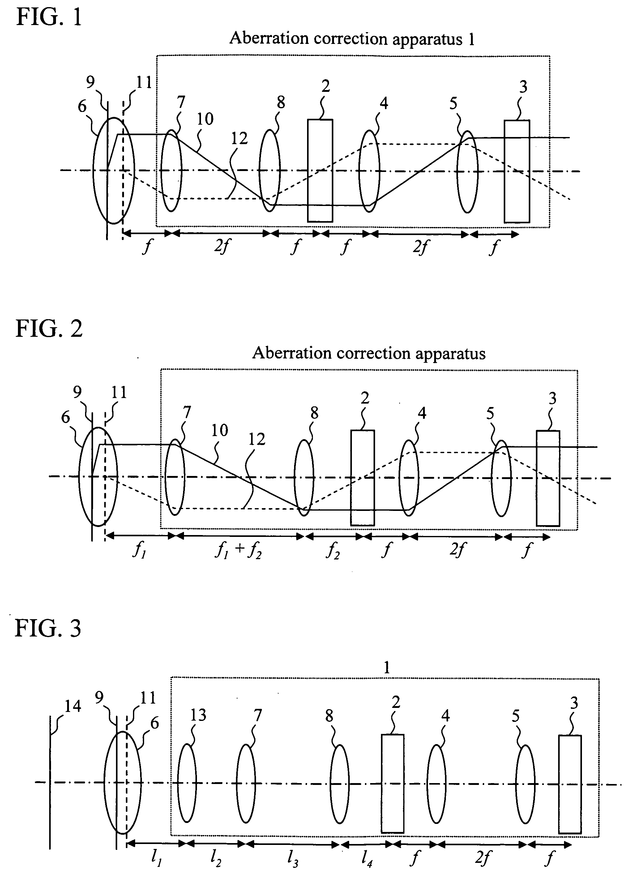
[0045]FIG. 3 shows the schematic configuration of an aberration correction apparatus according to an embodiment of the present invention. As shown in FIG. 3, in an aberration correction apparatus 1, rotationally symmetric lenses 4 and 5 are arranged between multiple lenses 2 and 3, and three rotationally symmetric lenses 7, 8, and 13 are arranged between an objective lens 6 and a multiple lens 2. The focal length of each of the rotationally s...


PUM


Abstract

To provide an aberration correction configuration that can realize both an aberration correction function for a long focus and an aberration correction function for a short focus. While having a conventional aberration correction apparatus configuration that has two rotationally symmetric lenses arranged between two multiple lenses, three rotationally symmetric lenses are disposed between an objective lens and a multiple lens instead of the conventional arrangement in which two rotationally symmetric lenses are disposed therebetween. When using the objective lens with a long focal length, aberrations are corrected using two rotationally symmetric lenses among three rotationally symmetric lenses disposed between the objective lens and the multiple lens. When using the objective lens with a short focal length, e.g. for high resolution observation, aberrations are corrected using two rotationally symmetric lenses of a different combination to those used for a long focus, among the three rotationally symmetric lenses disposed between the objective lens and the multiple lens.

Description

CLAIM OF PRIORITY[0001]The present application claims priority from Japanese patent application JP2008-064717 filed on Mar. 13, 2008, the content of which is hereby incorporated by reference into this application.BACKGROUND OF THE INVENTION[0002]1. Field of the Invention[0003]The present invention relates to an aberration correction apparatus and a charged particle apparatus, and more particularly to an optical system for correcting a spherical aberration of an objective lens, of a charged particle beam microscope typified by a transmission electron microscope with, for example, an aberration correction apparatus including multiple lenses and rotationally symmetric lenses.[0004]2. Background Art[0005]An electron lens that uses an electric field or a magnetic field to converge electron beams is essential in an electron microscope such as a scanning electron microscope (SEM), a transmission electron microscope (TEM), or a scanning transmission electron microscope (STEM). A lens that a...

Claims


Application Information

Patent Timeline
IPC IPC(8): H01J3/14
CPCH01J3/12H01J37/153H01J2237/28H01J2237/1534H01J37/26
Inventor HIRAYAMA, YOICHIYOSHIDA, TAKAHO
Owner HITACHI LTD
Why Eureka
Try Eureka