Current regulator and current control method and system for ac motors

a current regulator and motor technology, applied in the direction of motor/generator/converter stopper, dynamo-electric converter control, dynamo-electric gear control, etc., can solve problems such as instability, affecting the operation of current regulation, and introducing instability

Active Publication Date: 2009-09-17
GM GLOBAL TECH OPERATIONS LLC +2
View PDF1 Cites 27 Cited by
  • Summary
  • Abstract
  • Description
  • Claims
  • Application Information

AI Technical Summary

Benefits of technology

[0008]In another embodiment, a system is provided for controlling an AC motor. The system includes, but is not necessarily limited to, an inverter having an output configured to couple to the AC motor, and a controller coupled to the inverter. The inverter is configured to produce an AC voltage based on a commanded voltage and further configured to drive the AC motor at a fundamental frequency with the AC voltage. The AC motor produces a stator current based on the AC voltage. The controller has a sampling frequency and is configured to produce a commanded voltage based on a commanded current and a synchronous frame current. The commanded voltage is compensated for a delay and an anti-windup offset, where the delay becomes more significant as the ratio of the sampling frequency to the fundamental frequency decreases. The synchronous frame current is based on the stator current, and the anti-windup offset is associated with a pre-determined voltage limit.

Problems solved by technology

For example, delays in digital implementation, increased sub-harmonics in voltage synthesis using pulse width modulation (PWM), or the like, tend to introduce instability.
An increased pole-count generally increases the fundamental frequency associated with the AC motor, while the switching and sampling frequency associated with the current regulation is generally limited due to limitations of the switching power device and the through-put of the processor.
Furthermore, inner current loops associated with the current regulator may incur instability due to digital delays.

Method used


Image

  • Current regulator and current control method and system for ac motors
  • Current regulator and current control method and system for ac motors
  • Current regulator and current control method and system for ac motors

Examples


Embodiment Construction

[0015]The following detailed description is merely illustrative in nature and is not intended to limit the invention or the application and uses of the invention. Furthermore, there is no intention to be bound by any expressed or implied theory presented in the preceding technical field, background, brief summary or the following detailed description.

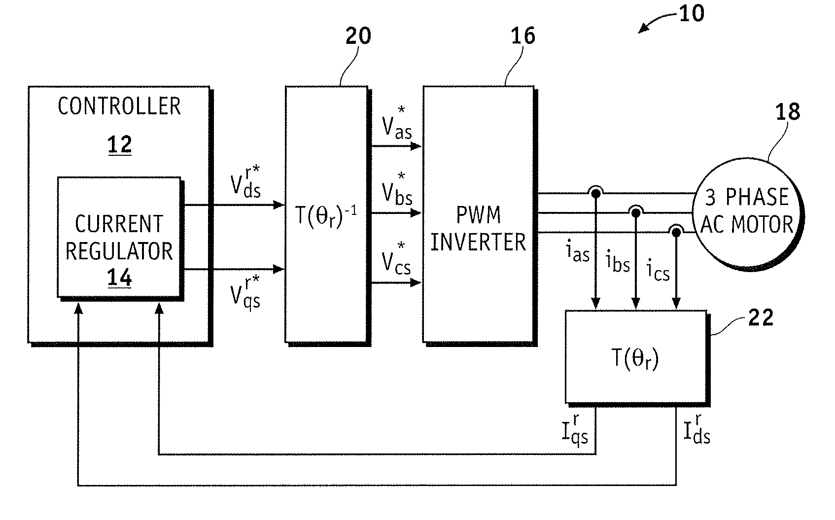
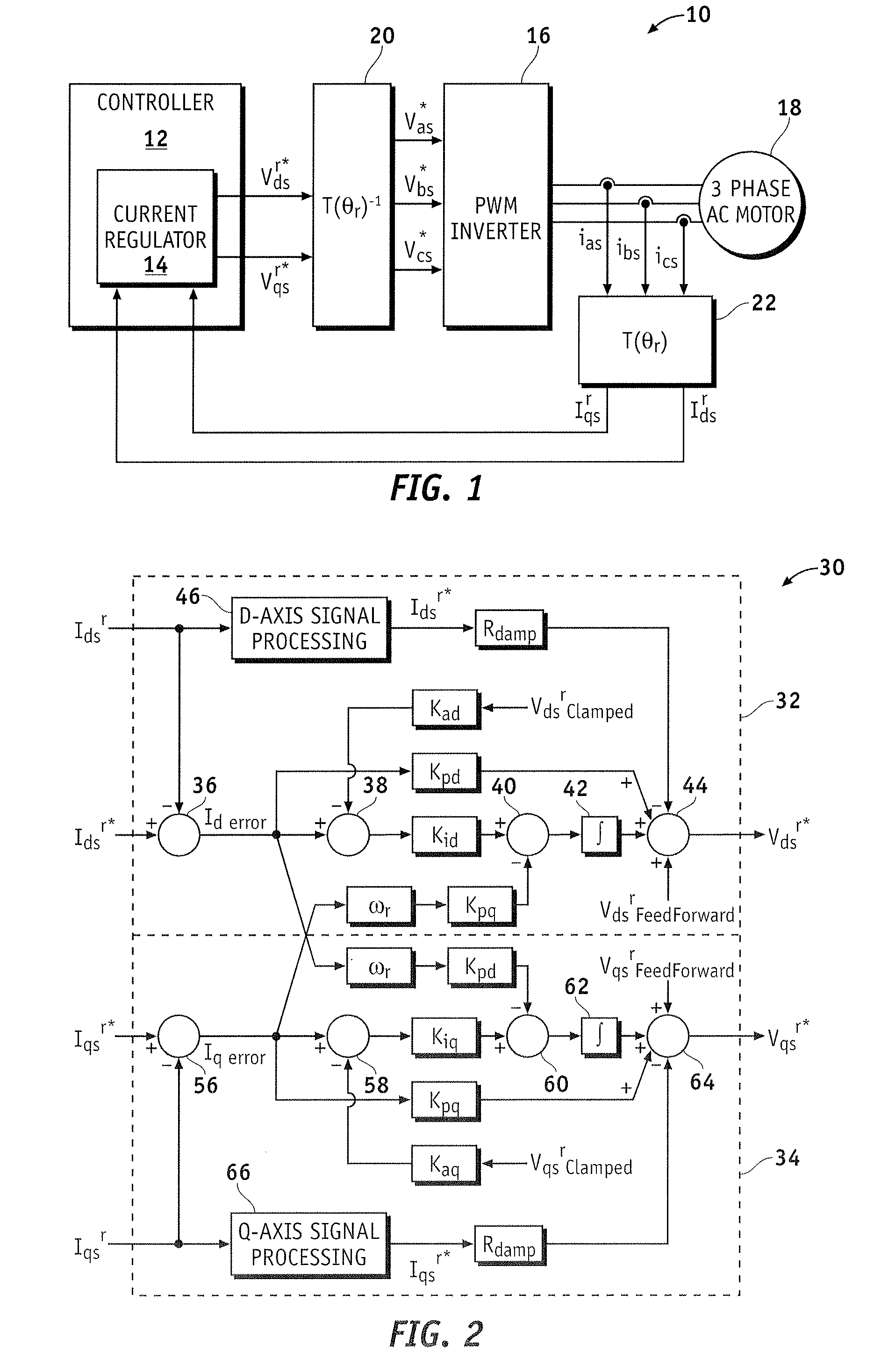
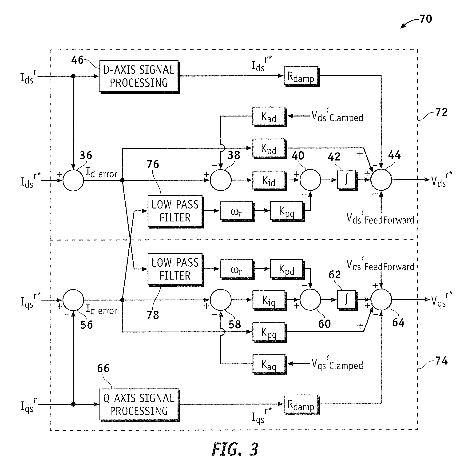
[0016]Systems, methods, and current regulators are provided for controlling an AC motor via current regulation. In one embodiment, complex vector current regulation with active damping resistance is used to control the AC motor. This current regulation utilizes at least one of current prediction, low-pass filtering, and anti-windup offset to improve control of the AC motor. Although the exemplary systems, current regulators, and methods are described with respect to an AC motor, these systems, current regulators, and methods may also be applied to other electric motors.

[0017]Referring to FIG. 1, a system 10 for controlling an AC motor 1...


PUM


Abstract

Methods and systems are provided for controlling an AC motor via an inverter. The method includes determining a delay-compensated offset based on a synchronous frame current, producing a current error based on a synchronous frame current and a commanded current, producing a voltage error based on an anti-windup offset and the current error, producing a commanded voltage based on the delay-compensated offset and the voltage error, and providing the inverter with the commanded voltage.

Description

TECHNICAL FIELD[0001]The present invention generally relates to controlling alternating current (AC) motors, and more particularly relates to apparatus, systems and methods for current control of AC motors.BACKGROUND OF THE INVENTION[0002]Synchronous frame current regulators are commonly used for current control of AC motors, such as three-phase electric motors. By providing dynamic control over a wide frequency range, synchronous frame current regulators are suited to many industrial applications. In digital implementations of conventional current regulators, as the ratio of the sampling frequency to the fundamental frequency, or synchronous frequency, of the AC motor decreases, the stability of these current regulators tends to decrease. For example, delays in digital implementation, increased sub-harmonics in voltage synthesis using pulse width modulation (PWM), or the like, tend to introduce instability.[0003]To produce high torque within a limited volume, a high pole-count elec...

Claims


Application Information

Patent Timeline
Patent Type & Authority Applications(United States)
IPC IPC(8): H02P21/14
CPCH02P21/0035H02P21/22
Inventor BAE, BONHOPATEL, NITINKUMAR R.SCHULZ, STEVEN E.NAGASHIMA, JAMES M.YIM, JUNG SIKSUL, SEUNG KI
Owner GM GLOBAL TECH OPERATIONS LLC
Why Eureka
Try Eureka