Crosslaminate of oriented films and methods and apparatus for manufacturing same

a technology of oriented films and crosslaminates, which is applied in the field of crosslaminates, can solve the problems of poor tear propagation resistance of thin crosslaminates, and inability to meet the requirements of users, so as to improve the pattern of bosses and webs, the effect of improving the tear propagation resistan

Active Publication Date: 2009-09-17
THE GLAD PROD CO
View PDF50 Cites 70 Cited by
  • Summary
  • Abstract
  • Description
  • Claims
  • Application Information

AI Technical Summary

Benefits of technology

[0015]It is now found that the thinner webs, when they are unbonded or only weakly bonded to the adjacent ply, provide a surprising improvement of the tear propagation resistance. This can be explained by the influence of these biaxially oriented narrow “lines” on the ability for change of orientation in the ply under the tearing forces. Such change of orientation serves to stop the tearing, and the narrow “lines” act as initiators for the re-orientation. Therefore it is also important to provide a pattern as fine as practically possible.
[0016]As mentioned above, a second objective of the invention is improvement of the aesthetics, and this is achieved by a textile-like appearance of the crosslaminated embossed

Problems solved by technology

Nevertheless, as the figure 30,000 tons annual production indicates, the success of crosslamination technology in the marketplace has been limited.
Due to the unbalanced orientation in the individual films and criss-crossing of the main directions of the orientation, one film will then have a tendency to propagate the tear in one direction and another film will tend to propagate the tear in another direction.
As a consequence of this “competition”, “thin” crosslami

Method used


Image

  • Crosslaminate of oriented films and methods and apparatus for manufacturing same
  • Crosslaminate of oriented films and methods and apparatus for manufacturing same
  • Crosslaminate of oriented films and methods and apparatus for manufacturing same

Examples


example 1

[0103]A 60 micrometre thick 3-layer tubular film is extruded, composed as follows:[0104]Middle layer, 80% of total: HDPE of m.f.i.=0.2 and density −0.944 g ml−1.[0105]Outer surface layer-lamination layer, 10% of total: 50% Affinity 8770 (a metalocene of m.f.i.=1.0.[0106]Interface surface layer, 10% of total: LLDPE of m.f.i.=2[0107]Blow ration: 1:1:1.[0108]Longitudinal drawn down ratio: 30:1.

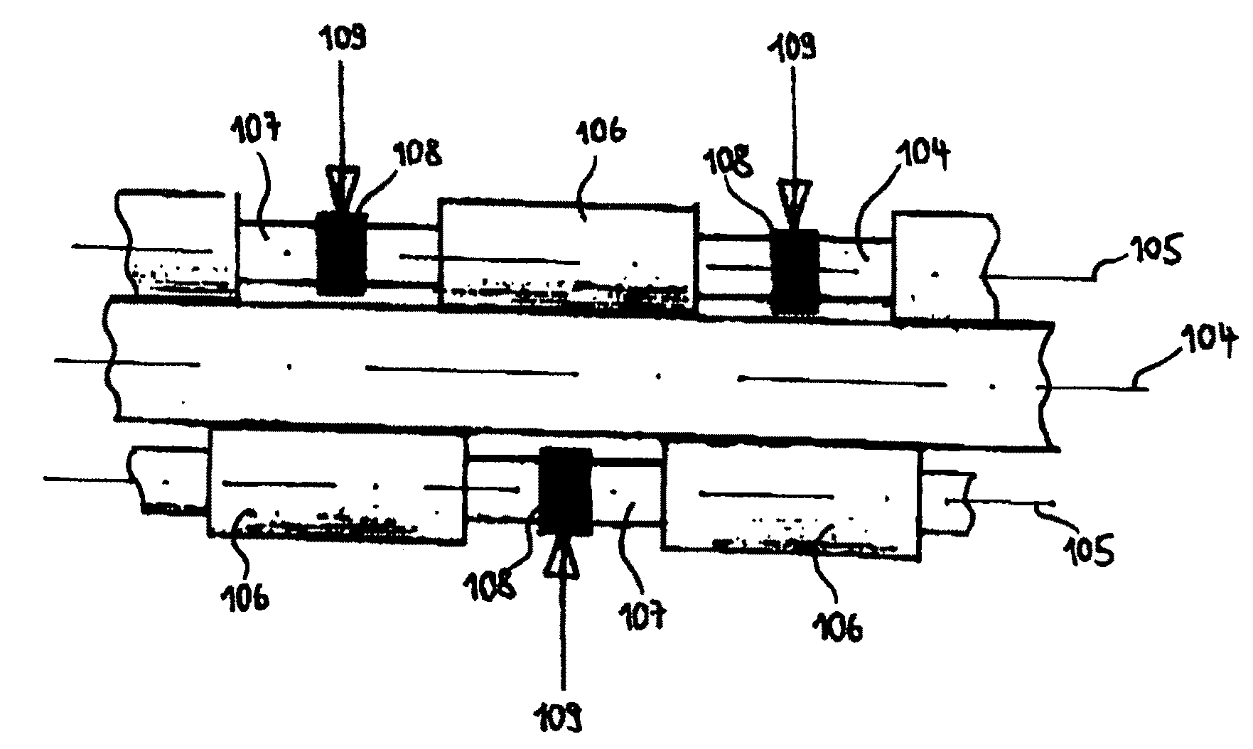
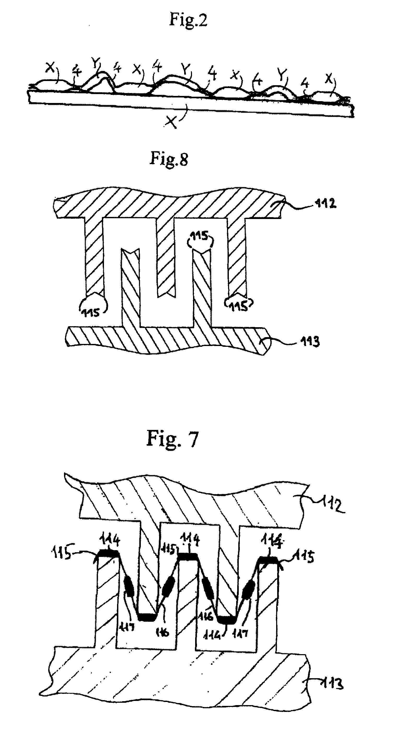
[0109]The tubular, uniaxially meltoriented film is semi-fibrillated at 40° C. (ambient temperature) between grooved rollers as shown in FIG. 7 with pitch 1.2 mm and with 0.3 mm distance from sharp edge to sharp edge on the crests. The downstream grooved roller moves 5% faster than the upstream one. It has quite generally been found that such small velocity difference helps to make the embossment (the segmental stretching) even. In immediate succession to these grooved rollers the tubular film is taken through a pair of intermeshing, driven grooved rollers of pitch 15 mm having rounded crests, adj...

example 2

[0116]An about 0.15 mm thick 2-layers tubular film is extruded, composed as follows:

[0117]Main layer, about 80% of total:[0118]HDPE of m.f.i.=about 0.2 and density=about 0.95 g ml−1.[0119]Outer surface layer=lamination layer, about 20% of total: an ethylene copolymer which starts melting at about 95° C.[0120]Blow ratio about 1:2:1.

[0121]The lay-flat tubular film is longitudinally stretched at about 30° C. in a ratio about 3:1, as measured after relaxation and stabilization by heat. This stretching is carried out in several steps between very closely spaced stretching rollers, as known in the art. After the stretching the gauge of the film is measure to be 0.040 mm. This cold-stretched tubular film is used for all crosslaminated samples produced in this example and in Example 3.

[0122]Comparative experiments are carried out as follows:[0123]a) the layflat longitudinally oriented tubular film is “semi-fibrillated”, helically cut at an angle of 45°, and then crosslaminated,[0124]b) simi...

example 3

[0130]This is carried out like Example 2, except for the lamination process which now takes place by the spot-bonding which in the description of FIG. 3 is referred to as “bonding system 3”. Only film cut at an angle of 63° is laminated. As in Example 2 crosslaminates with “semi-fibrillated” plies and crosslaminates with “non-semi-fibrillated” plies are compared.

[0131]The lamination / shrinking process and apparatus deviates from what is described in Example 1 with reference to FIG. 11, in that the rollers (12) and (13) are adapted to produce spot-bonding. The lamination roller (12) is a grooved roller with circular grooves of pitch 1.5 mm, having 0.5 mm thick, flat crests. The rubber-coated lamination roller (13) is also a grooved roller, but with axially extending grooves, pitch about 1.5 mm and having about 0.7 mm thick, flat crests. The hardness of these teeth is about 70 shoreA.

[0132]The temperature of the plies during lamination is adjusted to 1050° C. The lamination pressure an...


PUM

PropertyMeasurementUnit
Temperatureaaaaaaaaaa

Abstract

A crosslaminate is formed from two oriented plies of thermoplastic polymer material, arranged so that their orientation directions cross one another, the plies being heat sealed together. Each ply is semi-fibrillated, that is consist of linear thin regions of biaxially oriented material and thicker linear bosses between the thinner regions. The webs are sealed primarily through bonds formed at the intersection of the bosses (thicker regions). The array of bosses has a division less than 2 mm. The laminate has improved aesthetic and strength properties. A method for forming the crosslaminate involves segmental stretching of the material to form the thinner regions, and apparatus comprising intermeshing grooved stretching rollers having sharp-edged crests is described.

Description

RELATED APPLICATIONS[0001]This application is a nationalization of PCT / EP2006 / 062260, filed 11 May 2006, published as WO 2006 / 120238, published 16 Nov. 2006, which claims priority to PCT / EP2006 / 000281, filed 5 Jan. 2006 (Jan. 5, 2006), published as WO 2006 / 072604 A2 on 13 Jul. 2006 (Jul. 13, 2006), GB 0509615.1, filed 11 May 2005 (May 11, 2005) and GB 0511394.9, filed 3 Jun. 2005 (Jun. 3, 2005).BACKGROUND OF THE INVENTION[0002]1. Field of the Invention[0003]The present invention concerns crosslaminates.[0004]More particularly, the present invention concerns laminates of films of which at least two are uniaxially or unbalanced biaxially oriented, and in which the main direction of orientation in one of these films crosses the main direction in the other one.[0005]2. Description of the Related Art[0006]Crosslaminates of oriented films from synthetic polymer materials have been commercially produced since 1968, then mainly as described in GB-A-0792976 (Rasmussen) of May 23, 1955. To th...

Claims


Application Information

Patent Timeline
IPC IPC(8): B29C55/00B32B3/02B32B38/00C08J3/00B32B7/03
CPCB29C55/18Y10T428/24694B32B38/1825B32B2307/5825B32B27/12B29K2995/0051B29K2995/005B29C55/08B29C55/06B32B2250/20B32B2250/02Y10T428/24826Y10T428/24025Y10T428/24628B32B27/08B32B27/205B32B27/306B32B27/32B32B27/327B32B3/266B32B3/30B32B2270/00B32B2307/31B32B2307/50B32B2307/516B32B2307/518B32B2307/54B32B2307/718B32B2307/736B32B2307/75B32B2419/06B32B2437/00B32B2439/06B32B2439/46B32B2553/00B32B3/28B32B7/05B32B7/03
Inventor RASMUSSEN
Owner THE GLAD PROD CO
Why Eureka
Try Eureka