Applicator instruments having protective carriers for hemostats and methods therefor

a protective carrier and hemostat technology, applied in the field of bleeding control, can solve the problems of unsuitable endoscopic tube or trocar insertion, ineffective exposure to fluid, and disclosed inserting devi

Active Publication Date: 2009-09-17
ETHICON INC
View PDF35 Cites 26 Cited by
  • Summary
  • Abstract
  • Description
  • Claims
  • Application Information

AI Technical Summary

Benefits of technology

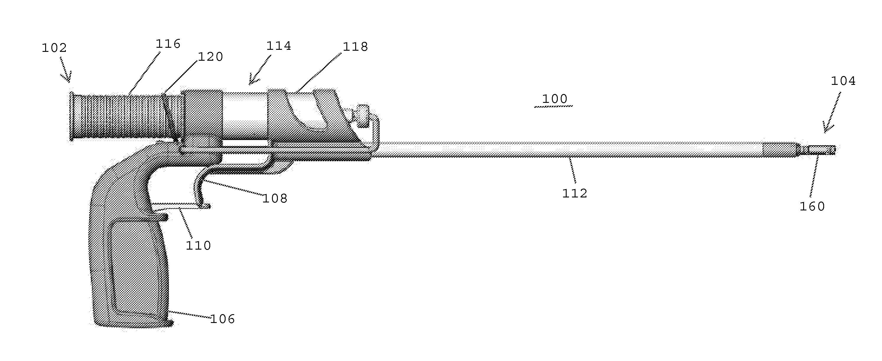
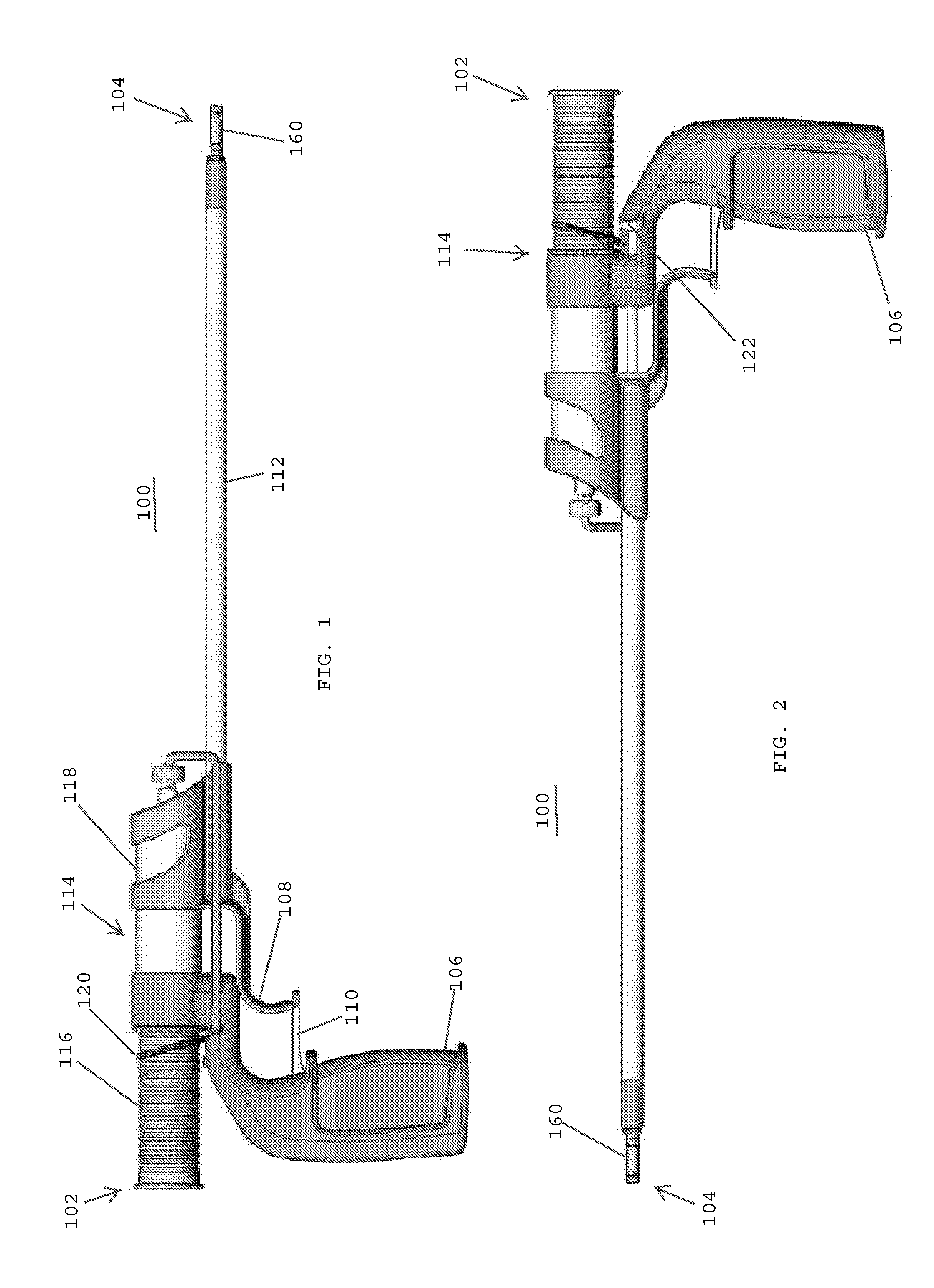
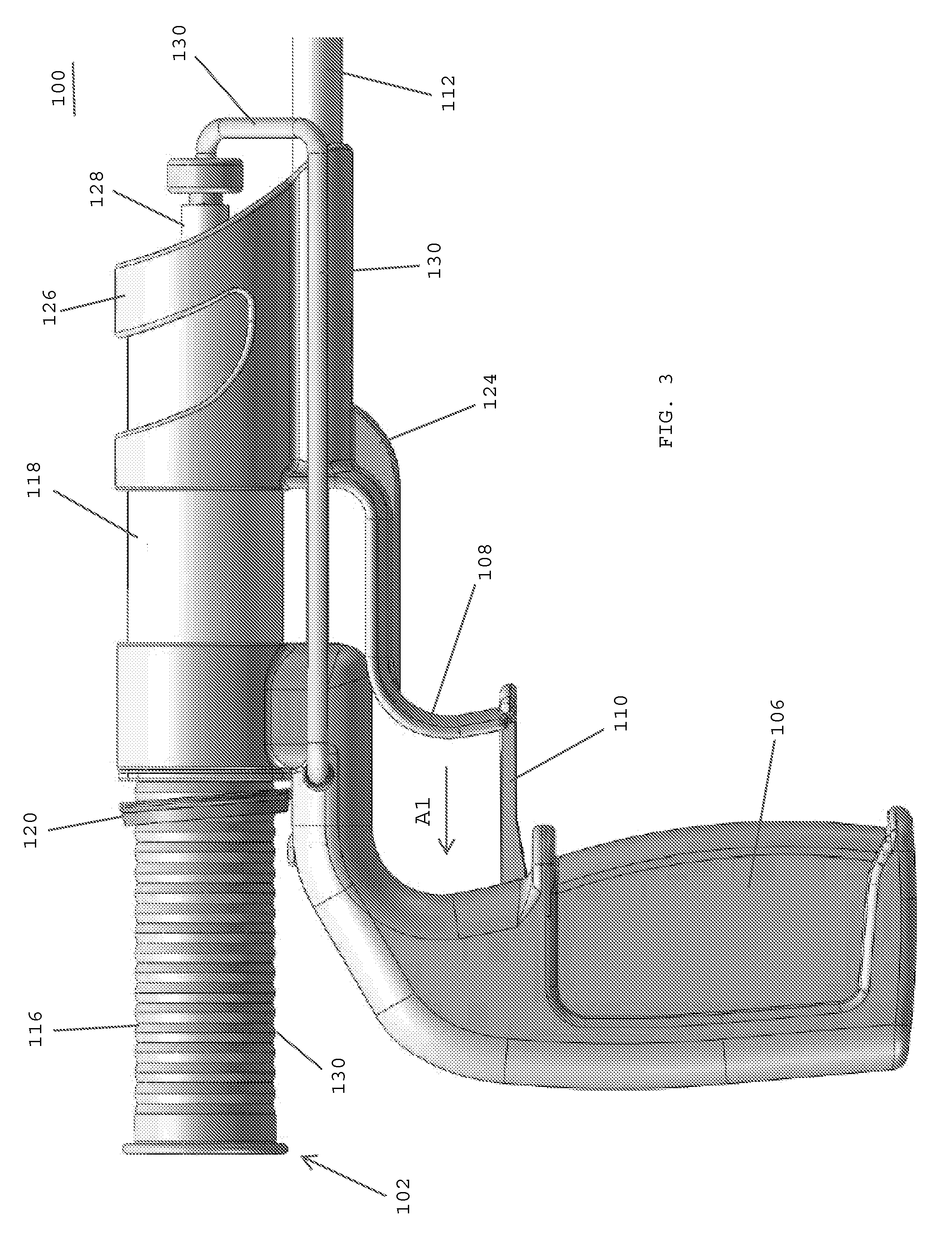
[0031]In one embodiment, an instrument for delivering a hemostat, such as a topically applied hemostat, includes an outer shaft having a proximal end and a distal end, a hemostat disposed at the distal end of the outer shaft, and a fluid-resistant element connected to the distal end of the outer shaft and surrounding the hemostat, whereby the fluid-resistant element has a breakable, fluid-resistant seal at a distal end thereof. The fluid-resistant element may be snap-fit onto the distal end of the outer shaft. The breakable, fluid-resistant seal may be a pierceable membrane, a rubber seal, or a cross-slit (four-way duckbill) valve. The fluid-resistant element may include a cartridge having a breakable, fluid-resistant seal at a distal end thereof. The cartridge may include a cartridge tube having a proximal end, a distal end, and a central opening extending between the proximal and distal ends thereof. The cartridge may also include the breakable, fluid-resistant seal covering the central opening at the distal end of the cartridge tube. In one embodiment, the cartridge tube has structure for connecting to the distal end of the outer shaft. The connecting structure may include one or more ridges, projections, bumps, grooves, depressions, a press-fit, and / or threads.
[0032]The instrument may also include the outer shaft having a central lumen extending to the distal end thereof, an intermediate shaft telescopically received within the central lumen of the outer shaft, the intermediate shaft having a proximal end, a distal end that extends distally from the distal end of the outer shaft, and a central lumen extending to the distal end thereof, and an inner shaft telescopically received within the central lumen of the intermediate shaft, the inner shaft having a proximal end and a distal end that extends distally from the intermediate shaft. The instrument may also include a balloon having a proximal end secured to the distal end of the intermediate shaft and a distal end secured to the distal end of the inner shaft, whereby the hemostat is disposed at the distal end of the inner shaft and the fluid-resistant element is connected to the distal end of the outer shaft and surrounds the hemostat for forming a fluid-resistant chamber around the hemostat.
[0033]In one embodiment, the instrument includes a first actuator coupled with the outer shaft for selectively moving the distal end of the outer shaft and the fluid-resistant element proximally for breaking the fluid-resistant seal and delivering the hemostat from the distal end of the instrument. The instrument may also include a second actuator for inflating the balloon, and a third actuator for moving the distal ends of the intermediate and inner shafts relative to one another for changing the shape of the inflated balloon.
[0034]In one embodiment, the instrument includes a cartridge loader having an upper end with a platform, and a central opening extending from the platform toward a lower end of the cartridge loader, whereby the central opening is adapted to receive the cartridge and the cartridge platform is adapted to receive a hemostat prior to loading the hemostat into the cartridge. The central opening of the cartridge loader desirably has a closed end with a support surface that conforms to the fluid-resistant seal at the distal end of the cartridge.
[0035]In one embodiment, an instrument for controlling bleeding includes an outer shaft having a proximal end, a distal end, and a central lumen extending to the distal end thereof, an intermediate shaft telescopically received within the central lumen of the outer shaft, the intermediate shaft having a proximal end, a distal end, and a central lumen extending to the distal end thereof, and an inner shaft telescopically received within the central lumen of the intermediate shaft, the inner shaft having a proximal end and a distal end that extends distally from the intermediate shaft. The instrument also desirably includes a hemostat disposed at the distal end of the inner shaft, and a water-resistant element connected to the distal end of the outer shaft and surrounding the hemostat, whereby the water-resistant element has a breakable, water-resistant seal at a distal end thereof.
[0036]In one embodiment, an instrument for controlling bleeding includes an outer shaft having a proximal end and a distal end, a balloon disposed at the distal end of the outer shaft, a hemostat disposed adjacent to balloon, and a fluid-resistant element secured to the distal end of the outer shaft and surrounding the hemostat to form a fluid-resistant compartment around the hemostat, whereby the fluid-resistant element has a breakable, fluid-resistant seal at a distal end thereof.

Problems solved by technology

The inserter device disclosed in the '395 patent, however, is not suitable for insertion through an endoscopic tube or trocar.
In addition, there remains a need for instruments and methods for the delivery, deployment, and tamponade of medical textiles having moisture-sensitive components (e.g. moisture-sensitive adhesives), which may become ineffective when exposed to fluids or moisture before reaching a target tissue site.

Method used


Image

  • Applicator instruments having protective carriers for hemostats and methods therefor
  • Applicator instruments having protective carriers for hemostats and methods therefor
  • Applicator instruments having protective carriers for hemostats and methods therefor

Examples


Embodiment Construction

[0075]The invention disclosed herein is not limited in its application or use to the details of construction and arrangement of parts illustrated in the accompanying drawings and description. The illustrative embodiments of the invention may be implemented or incorporated in other embodiments, variations and modifications, and may be practiced or carried out in various ways.

[0076]The headings used herein are for organizational purposes only and are not meant to limit the scope of the description or the claims. As used throughout this application, the word “may” is used in a permissive sense (i.e., meaning having the potential to), rather than the mandatory sense (i.e., meaning must). Similarly, the words “include”, “including”, and “includes” mean including but not limited to. To facilitate understanding, like reference numerals have been used, where possible, to designate like elements common to the figures.

[0077]Referring to FIGS. 1 and 2, a system for the delivery, deployment, an...


PUM


Abstract

An instrument for controlling bleeding includes an outer shaft having a proximal end, a distal end, and a central lumen extending to the distal end thereof, an intermediate shaft telescopically received within the central lumen of the outer shaft, the intermediate shaft having a proximal end, a distal end, and a central lumen extending to the distal end thereof, and an inner shaft telescopically received within the central lumen of the intermediate shaft, the inner shaft having a proximal end and a distal end that extends distally from the intermediate shaft. The instrument includes a hemostat disposed at the distal end of the inner shaft, and a fluid-resistant element connected to the distal end of the outer shaft and surrounding the hemostat. The fluid-resistant element has a breakable, fluid-resistant seal at a distal end thereof that protects the hemostat from fluids until the hemostat is delivered and deployed onto tissue. In one embodiment, the instrument includes an inflatable balloon to deploy and tamponade a hemostat.

Description

CROSS REFERENCE TO RELATED APPLICATIONS[0001]The present application is related to commonly assigned U.S. patent application Ser. No. ______, entitled “APPLICATOR INSTRUMENTS FOR THE DELIVERY, DEPLOYMENT, AND TAMPONADE OF HEMOSTATS AND METHODS THEREFOR” (Attorney Docket No. ETH5372USNP), filed on even date herewith, the disclosure of which is hereby incorporated by reference herein.BACKGROUND OF THE INVENTION[0002]1. Field of the Invention[0003]The present application is generally related to controlling bleeding, and is more specifically related to systems, instruments, and methods used for the delivery, deployment, and tamponade of hemostats.[0004]2. Description of the Related Art[0005]Medical textiles are used during surgical procedures to control bleeding, minimize blood loss, reduce post-surgical complications, and shorten the duration of surgery. Commonly used medical textiles include adhesion barriers, sponges, meshes, and hemostatic wound dressings that are applied to the sur...

Claims


Application Information

Patent Timeline
Patent Type & Authority Applications(United States)
IPC IPC(8): A61M29/02A61M31/00
CPCA61B17/00234A61F2002/0072A61B2017/00659A61B2017/00544A61M37/0069A61B19/026A61B2017/00884A61B17/0057A61B2017/0053A61B17/00491A61B2017/00623A61B2017/00575A61B2017/00557A61B17/3468A61B50/30
Inventor GABEL, JONATHANLIVINGSTON, JASON C.LOONEY, DWAYNEGUGLIELMO, MICHAEL E.FURNISH, GREG R.MISER, JOHN
Owner ETHICON INC
Why Eureka
Try Eureka