Surveying device and surveying system

a technology of surveying system and surveying device, which is applied in the direction of distance measurement, using reradiation, instruments, etc., can solve the problems of short measuring time of one measurement, reduced optical intensity of each distance measurement light, and reduced measurement accuracy, so as to achieve the effect of simple construction

Active Publication Date: 2009-09-24
KK TOPCON
View PDF13 Cites 25 Cited by
  • Summary
  • Abstract
  • Description
  • Claims
  • Application Information

AI Technical Summary

Benefits of technology

[0023]Further, the present invention provides the surveying system as described above, wherein the projecting light switchover unit comprises an extension member for increasing a spreading angle in vertical direction of the distance measuring light and a means for inserting and removing the extension member to or from a distance measuring optical axis. As a result, the surveying device is in a simple construction and the distance measuring light can be projected by selecting from the fan-shaped distance measuring light with spreading angle in vertical direction, the spot-type distance measuring light with parallel beams or the fan-shaped distance measuring light with a different spreading angle.

Problems solved by technology

As a result, an optical intensity of each of the distance measuring light is decreased, and influence of noise light becomes stronger, and this leads to lower measurement accuracy.
Further, because the distance measuring light is rotated at high velocity, a measuring time of one measurement is short.
Also, there are not many distance measurement data to be averaged, and it is not possible to improve the measurement accuracy.
Thus, these are a problem that the distance which can be measured is lengthen, and other problems.
The measurement can be made with high accuracy and a working efficiency of the measurement is also high, but it is not possible to perform measurements at a multiple points at the same time.
As a result, in case it is necessary to perform measurements on a multiple points at the same time, the working efficiency is extremely decreased.

Method used


Image

  • Surveying device and surveying system
  • Surveying device and surveying system
  • Surveying device and surveying system

Examples


Embodiment Construction

[0033]A description will be given below on the best mode for carrying out the present invention by referring to the attached drawings.

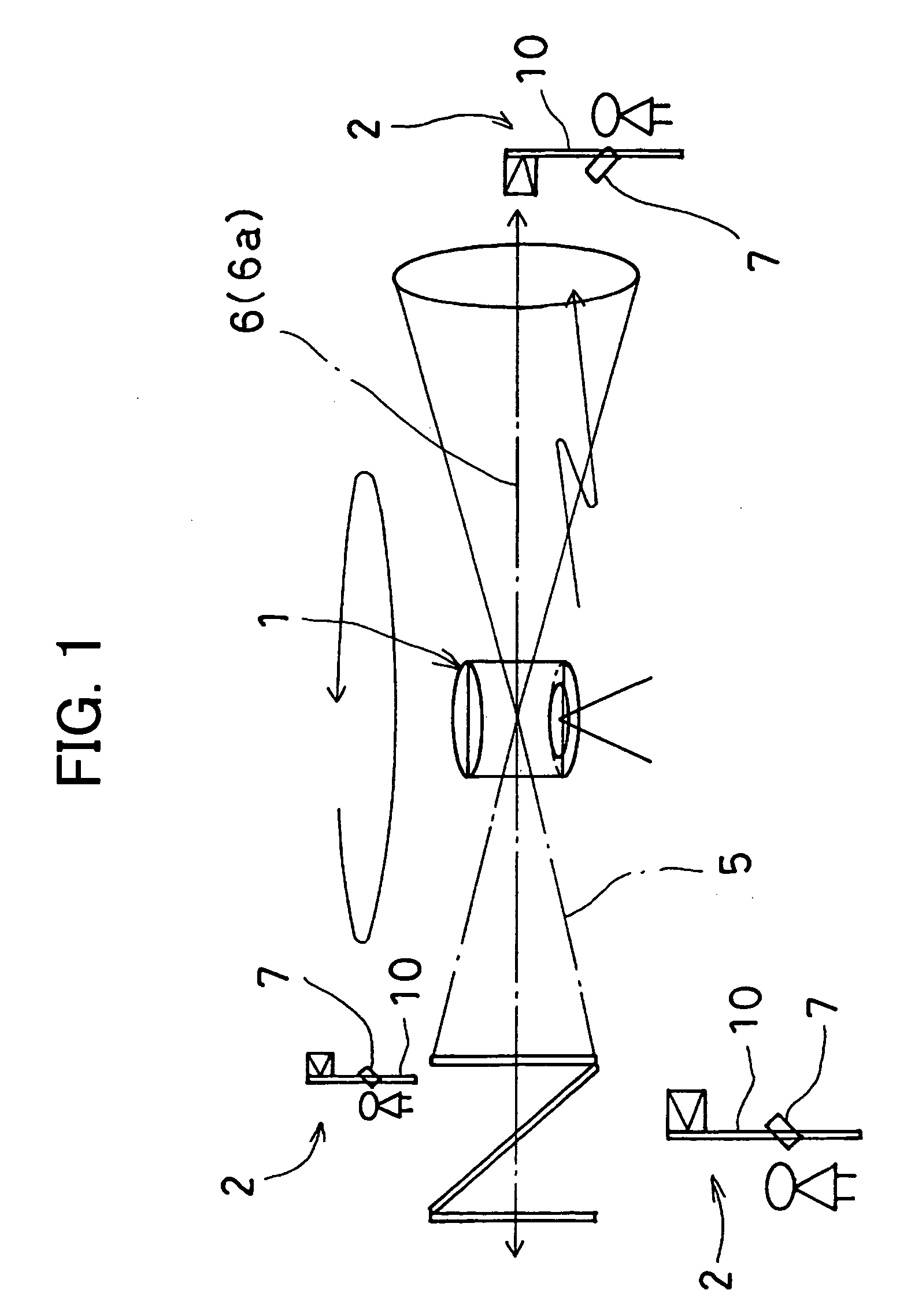
[0034]First, referring to FIG. 1 and FIG. 2, a description will be given on general features of a surveying system in an embodiment of the present invention.

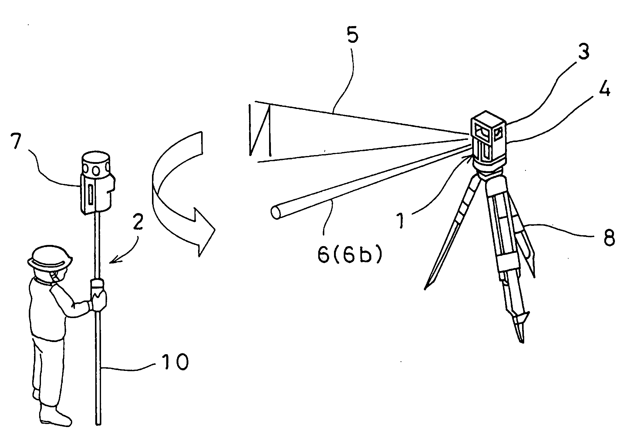
[0035]The surveying system comprises a surveying device 1 and at least one photodetection device 7. The surveying device 1 and the photodetection device 7 can give and take data to and from each other via a communication means.

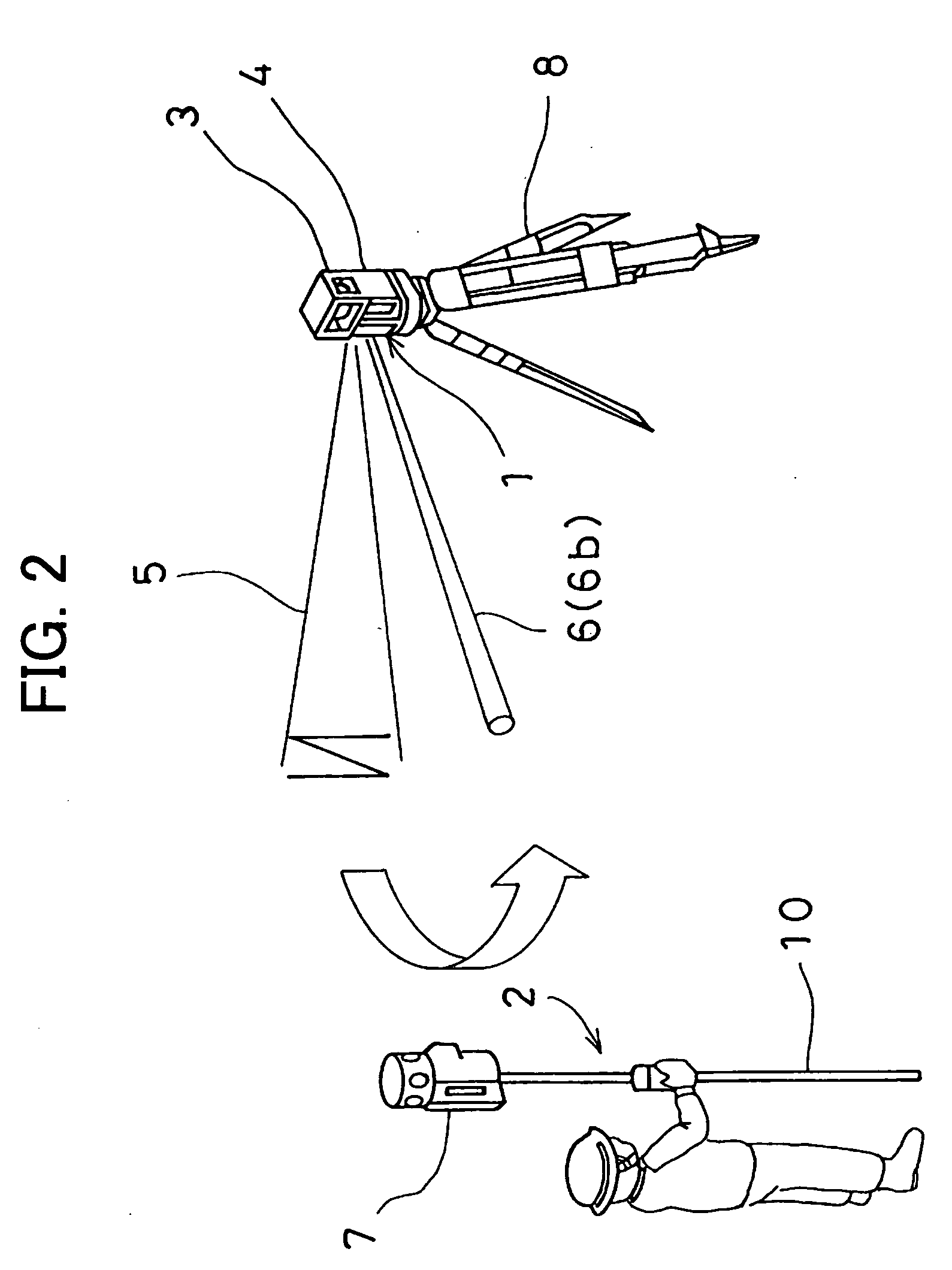
[0036]FIG. 1 shows a case where the multi-measurement is performed by using the surveying device 1 and a plurality of objects 2 to be measured.

[0037]The surveying device 1 is installed at a known point via a tripod 8 and can project laser beams 5 for forming a reference plane at a constant velocity in rotary irradiation and can project distance measuring light 6 in rotary irradiation. Each of the objects 2 to be measured has the photodetection device 7, including a reflectio...


PUM


Abstract

The present invention provides a surveying device, which comprises rotators 53, 56 and 61 for deflecting a distance measuring light in horizontal direction and for projecting the distance measuring light in rotary irradiation, at least one extension member 62 for increasing a spreading angle in vertical direction of the distance measuring light, and a means for attaching or detaching the extension member so that the extension member can be inserted and removed to or from a distance measuring optical axis.

Description

BACKGROUND OF THE INVENTION[0001]The present invention relates to a surveying device and a surveying system when a surveying operation is performed by a single surveying operator or by cooperation of two or more surveying operators.[0002]In a surveying operation performed in a civil engineering work, e.g. a surveying operation in a road construction, a measurement is performed on positions on both sides of the road, on a difference in elevation, on a width of the road, etc., and a plurality of measuring points are measured at the same time. As a result, the surveying operation is a cooperative operation to be performed by two or more surveying operators.[0003]A surveying device, by which measurement can be made on a plurality of measuring points at the same time, is disclosed in JP-A-2006-337302.[0004]In a surveying device according to JP-A-2006-337302, laser beams for forming reference plane including three or more fan-shaped laser beams, with at least one of the laser beams being ...

Claims


Application Information

Patent Timeline
Patent Type & Authority Applications(United States)
IPC IPC(8): G01C15/06G01C3/08
CPCG01C3/02G01S17/42G01C15/002
Inventor HAYASHI, KUNIHIROOHTOMO, FUMIOKUMAGAI, KAORU
Owner KK TOPCON
Why Eureka
Try Eureka