Fuel injector isolator

Inactive Publication Date: 2009-09-24
DELPHI TECH INC
View PDF19 Cites 23 Cited by
  • Summary
  • Abstract
  • Description
  • Claims
  • Application Information

AI Technical Summary

Benefits of technology

[0014]In a further aspect of the invention, the spacer is formed of a powder metal. The voids in the powder metal provide a thermally non-conductive substrate. Notches formed on

Problems solved by technology

However, direct metal-to-metal contact between the bottom surface of the DFI body and the top surface of the shoulder allows for unmitigated transfer of the vibration from the DFI to the cylinder head and allows for the transfer of heat by thermal conduction from the cylinder head to the DFI.
Allowing the vibration from the DFI to propagate into the combustion chamber can adversely effect the placement of the highly precise fuel spray pattern into the combustion chamber.

Method used


Image

  • Fuel injector isolator
  • Fuel injector isolator
  • Fuel injector isolator

Examples


Embodiment Construction

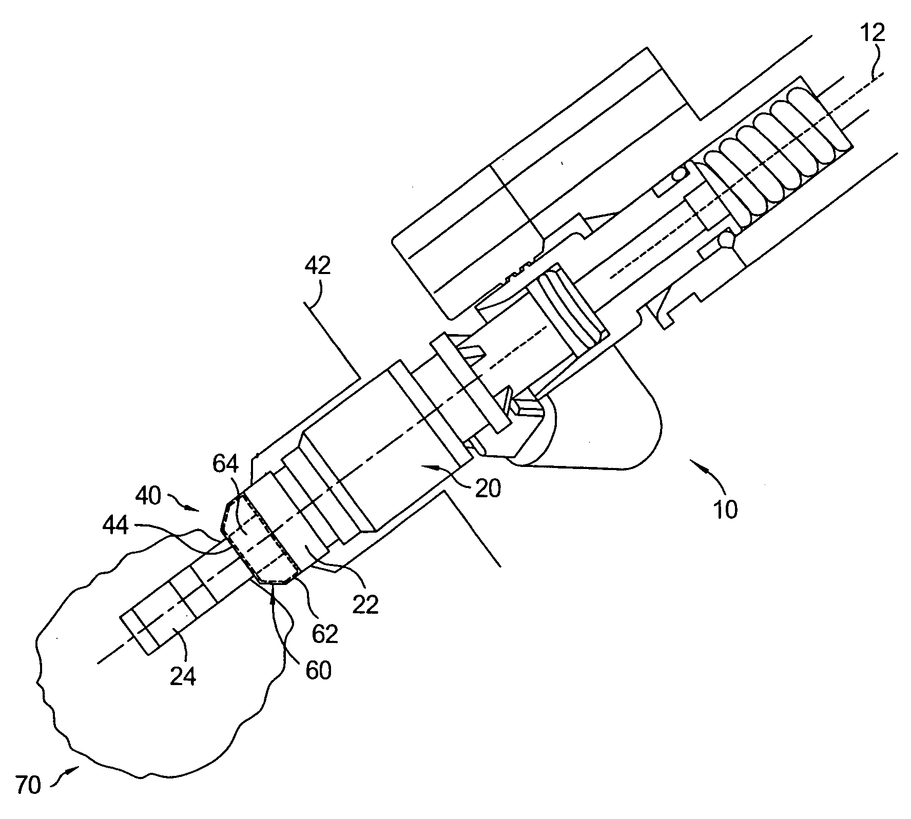
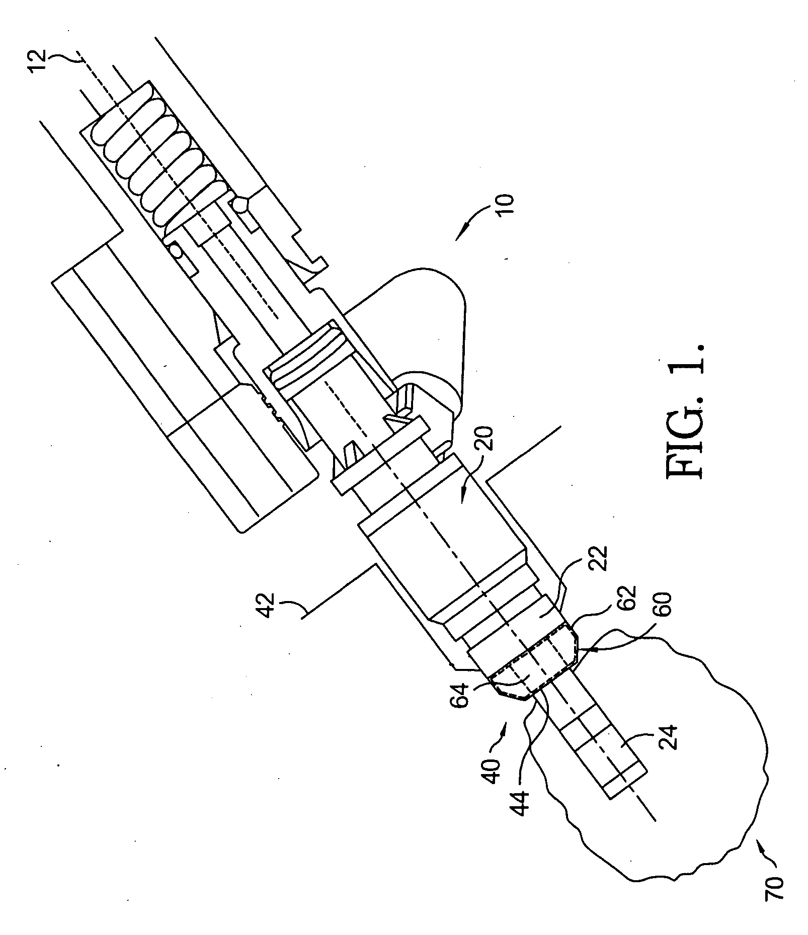
[0027]Referring to FIG. 1, a fuel injector-cylinder head assembly 10 of an internal combustion engine 70 includes a fuel injector 20, a cylinder head 40, and a compression resistant isolator 60 assembled there between. Fuel injector-cylinder head assembly 10 extends along an axis 12.

[0028]Fuel injector 20 includes a lower housing 22 and an injector tip 24 axially extending from lower housing 22. Cylinder head 40 includes a stepped housing 42 having a center opening 44. Fuel injector 20 is assembled in stepped housing 42 of cylinder head 40, such that stepped housing 42 of cylinder head 40 accommodates lower housing 22 of fuel injector 20 and such that injector tip 24 extends through center opening 44 of cylinder head 40. Fuel injector 20 may be, but is not limited to, a fuel injector for direct injection as shown in FIG. 1.

[0029]Isolator 60 is positioned within stepped bore 42 such that isolator 60 is positioned adjacent to lower housing 22 encircling injector tip 24. Accordingly, i...


PUM


Abstract

A compression resistant isolator disposed between a direct fuel injector and a cylinder head of an internal combustion engine provides thermal, or thermal and vibrational isolation therebetween. A plurality of radially spaced rigid axial support members provide axial load support to maintain proper direct fuel injector positioning within the cylinder head bore. Spaces formed between the rigid axial support members may have isolation materials positioned therein. The implementation of the isolator may reduce the operating temperature of a fuel injector for direct injection, which is critical to avoid injector tip plugging.

Description

TECHNICAL FIELD[0001]The present invention relates to fuel injection systems of internal combustion engines; more particularly, to fuel injectors for direct injection; and most particularly to a device and method for thermal and acoustic isolation of a fuel injector from a cylinder head.BACKGROUND OF THE INVENTION[0002]Fuel injector systems that deliver fuel to the combustion chamber of an internal combustion engine have been known for many years. The typical fuel injection system draws fuel from a fuel tank to a fuel rail mounted adjacent to the cylinder bank of the engine. The fuel injectors are electromechanical devices that deliver fuel in precise amounts and times to the respective cylinder.[0003]While the engine is running, the valve within each fuel injector is constantly being operationally cycled from an opened to a closed position. High frequency vibration is generated by the mechanical movement of the injector valves and low frequency pressure waves are generated by the m...

Claims


Application Information

Patent Timeline
IPC IPC(8): F02M61/16
CPCF02M53/046F02M2200/16F02M61/14
Inventor SHORT, JASON C.
Owner DELPHI TECH INC
Why Eureka
Try Eureka