Vehicle Door Structure

a technology for vehicles and doors, applied in the field of vehicle door structures, can solve the problems of increasing flexural rigidity inevitably involving an increase in the weight of the reinforcement beam, so as to achieve the expansion of the rigidity, the strength, and the regions able to receive the load

Inactive Publication Date: 2009-09-24
TOYOTA JIDOSHA KK
View PDF45 Cites 16 Cited by
  • Summary
  • Abstract
  • Description
  • Claims
  • Application Information

AI Technical Summary

Benefits of technology

[0006]It is an object of the invention to provide a vehicle door structure capable of avoiding the weight increase, the man-hour increase, and the door thickness increase involved with the addition of another member such as a reinforcement beam or the like.
[0011]In the vehicle door structure of the invention, the inner panel may further comprise a third coupling portion that is disposed on the perimeter of the door so as to couple the door and the vehicle body, and may further have a subsidiary reinforcement work portion that branches from the reinforcement work portion and that extends toward the third coupling portion. According to this aspect, since the subsidiary reinforcement work portion adds to the crash load transfer paths, the regions able to receive crash load can be further enlarged. Furthermore, the mechanical characteristics of the inner panel, such as the rigidity, the strength, etc., will improve. Similar to the reinforcement work portion, the subsidiary reinforcement work portion may be constructed of a rib as described above, or may also be constructed of a subsidiary bead that is protruded on the obverse side or the reverse side of the inner panel. The construction of the subsidiary reinforcement work portion may be the same as or different from that of the reinforcement work portion.
[0012]In the vehicle door structure of the invention, the inner panel may further comprise third and fourth coupling portions that are disposed on sides of the perimeter of the door that are different from each other so as to couple the door and the vehicle body, and may have another reinforcement work portion that extends so as to substantially connect the third coupling portion and the fourth coupling portion and that intersects with the aforementioned reinforcement work portion. According to this aspect, since the two intersecting reinforcement work portions add to the crash load transfer paths, the regions able to receive crash load can be further enlarged. Furthermore, the mechanical characteristics of the inner panel, such as the rigidity, the strength, etc., will improve.
[0013]As described above, according to the invention, crash load is converted into tensions that act in the reinforcement work portion, and is thus received by the inner panel. Therefore, it becomes possible to take crash countermeasures without attaching a separate member, such as a reinforcement beam or the like, to the inner panel.

Problems solved by technology

Furthermore, although in the construction in which a separate member, such as a reinforcement beam or the like, is attached to the inner panel, the capacity for crash load can be increased by improving the flexural rigidity of the reinforcement beam, the improvement of the flexural rigidity of the reinforcement beam inevitably involves an increase in the weight of the reinforcement beam.

Method used


Image

  • Vehicle Door Structure
  • Vehicle Door Structure
  • Vehicle Door Structure

Examples


first embodiment

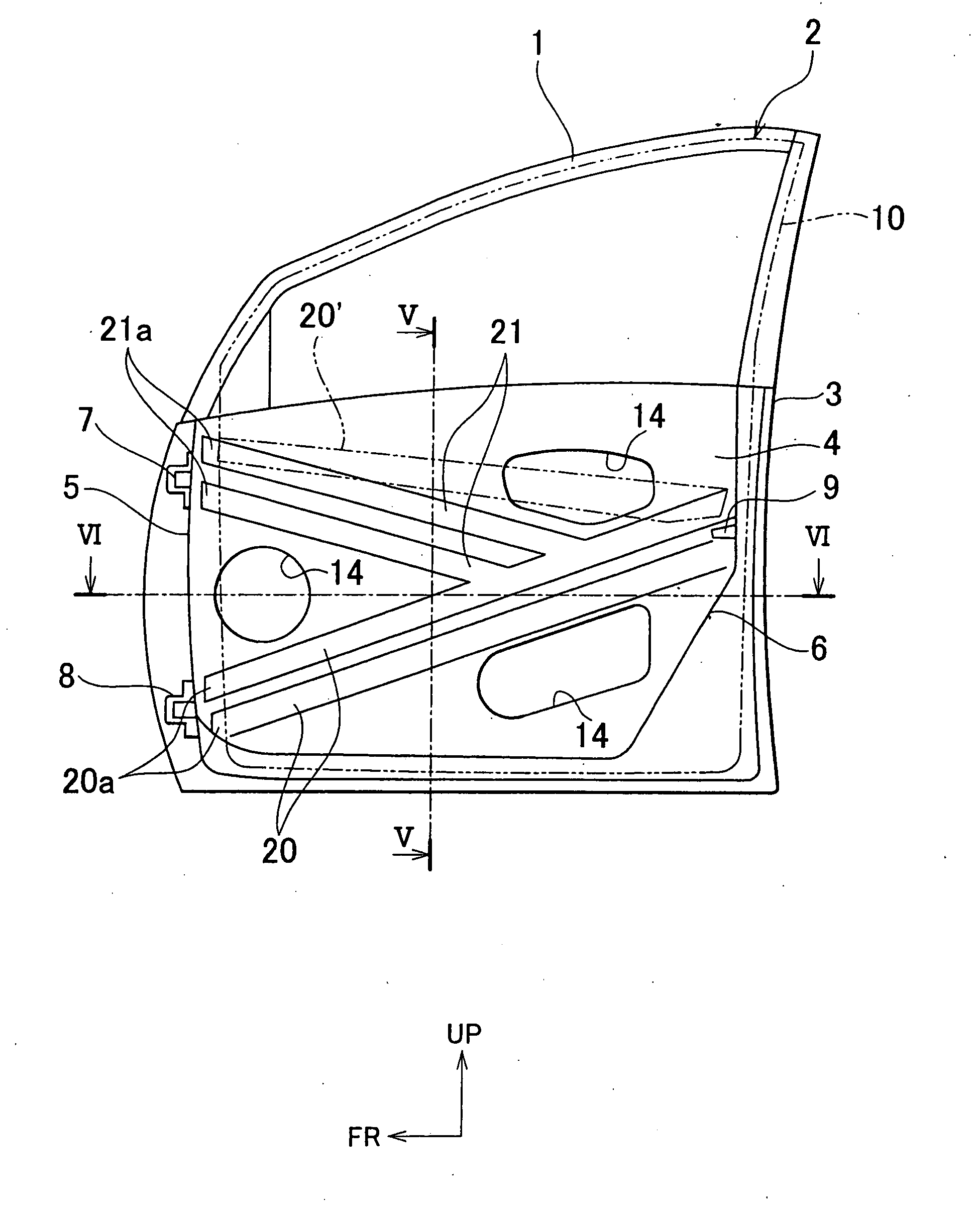
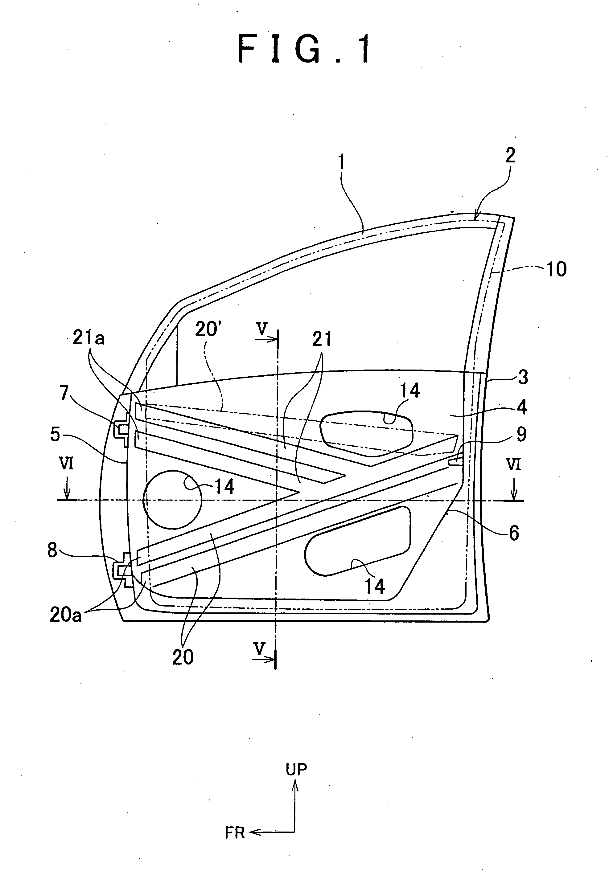
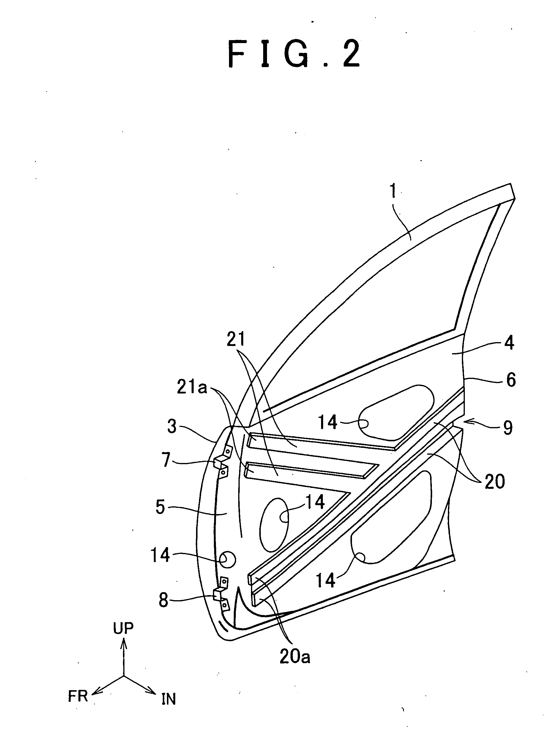
[0024]FIGS. 1 to 6 show an embodiment of a vehicle side door (hereinafter, sometimes referred to simply as “door”) to which the vehicle door structure of the invention is applied. FIG. 1 is a front view of a door 1; FIG. 2 is a perspective view of the door 1; FIG. 3 is a side view of the door 1 viewed from forward of the vehicle; FIG. 4 is a side view of the door 1 viewed from rearward of the vehicle; FIG. 5 is a sectional view taken on line V-V in FIG. 1; and FIG. 6 is a sectional view taken on line VI-VI in FIG. 1. It is to be noted herein that in these drawings, FR, UP and IN indicate a forward direction of the vehicle, an upward direction of the vehicle, and a laterally inward direction of the vehicle, respectively (this applies to other drawings as well).

[0025]As shown in FIGS. 1 to 4, the door 1 is formed by combining an outer panel 3 disposed at an outer side of a vehicle body 2 in the lateral direction of the vehicle, and an inner panel 4 disposed at an inner side of in the ...

second embodiment

[0031]FIG. 10 is a front view showing a second embodiment of the invention. Hereinafter, the same constructions as in the first embodiment are assigned with the same reference numerals in FIG. 10, and redundant descriptions will be avoided below. As shown in FIG. 10, a door 1′ of this embodiment has a subsidiary latch 15 that is added as a fourth coupling portion that is positioned lower, in the vehicle, than a lock portion 9. An inner panel 4′ has a bead 20 that extends so as to substantially connect an upper hinge 7 and the subsidiary latch 15, and another bead 20 that extends so as to substantially connect a lower hinge 8 and the lock portion 9. These beads intersect with each other in a substantially central portion of the inner panel 4′ so as to form an X-shape bead pattern. The subsidiary latch 15 is added in order to enhance the coupling between the door 1 and the vehicle body 2, and is a well-known mechanism capable of coupling the door 1 and the vehicle body and discontinui...


PUM


Abstract

A vehicle door structure comprises an inner panel (4) provided with an upper hinge (7), a lower hinge (8) and a lock portion (9) that are disposed on sides of a perimeter of a door (1) that are different from each other so as to couple the door (1) and a vehicle body (2). The inner panel (4) is reinforced by two beads (20, 20) that extend so as to substantially connect the lower hinge (8) and the lock portion (9), and that protrude inward in the lateral direction of the vehicle, and by two subsidiary beads (21, 21) that branch from a substantially central portion of a bead (20) and extend toward the upper hinge (7), and that protrude inward in the lateral direction of the vehicle.

Description

BACKGROUND OF THE INVENTION[0001]1. Field of the Invention[0002]The invention relates to a vehicle door structure.[0003]2. Description of Related Art[0004]As a door structure provided for a vehicle, there exists a structure in which a reinforcement beam extending from an upper hinge of a side door or from a location adjacent thereto toward a vicinity of the door striker is attached to an inner panel by spot welding (e.g., Japanese Translation of PCT International Application No. 2004-520224).[0005]The foregoing door structure is designed so that at the time of a side crash of the vehicle, the reinforcement beam bears crash load input to the door, and transfers it to a vehicle body pillar. However, the addition of such a reinforcement beam increases the weight of the door, and the man-hours for attachment of the reinforcement beam. Furthermore, in conjunction with securement of a space needed for installation of various devices within the door, there is fear that the addition of a re...

Claims


Application Information

Patent Timeline
Patent Type & Authority Applications(United States)
IPC IPC(8): B60J5/04
CPCB60J5/0426B60J5/0427B60J5/0455B60J5/0448B60J5/0429B60J5/0431B60J5/0433B60J5/045B62D25/02B60Y2200/11
Inventor SHIBASAKI, SHINICHI
Owner TOYOTA JIDOSHA KK
Why Eureka
Try Eureka