Rapid scan LADAR 3D imaging with compact digital beam formation

a 3d imaging and digital beam technology, applied in surveying, distance measurement, instruments, etc., can solve the problems of limited solid angle coverage, limited angular coverage, and long ladar search time of a volum

Active Publication Date: 2009-09-24
RAYTHEON CO
View PDF1 Cites 39 Cited by
  • Summary
  • Abstract
  • Description
  • Claims
  • Application Information

AI Technical Summary

Benefits of technology

[0008]Above limitations are avoided by a LADAR system for coherently imaging a target comprising a laser transmitter illuminating said volume with a laser beam modulated with a frequency. A receiver having isothermal contours, receives calibration reflections of said laser beam from a calibration reflector for calibration purposes. After calibration, target reflections arrive from the target. The receiver has a clock for distributing time stamps within the receiver or a similar means for referencing a time interval to a time reference. The receiver has a plurality of lenses mechanically coupled to a rigid frame. Each lens of said plurality of lenses is optically connected to one detector of a plurality of detectors. Each of the detectors mix the incoming optical input from its associated lens with a signal from the local oscillator.

Problems solved by technology

One aspect of the complexities of LADAR high frequency operation is the spatial coverage of a transmitted pulse.
Thus, the illumination / reception pattern of a single LADAR pulse has limited solid angle coverage.
This limited angular coverage forces LADAR systems to emit multiple pulses and make multiple scans to cover a volume where a target of interest might be located.
Because of these constraints, LADAR search times of a volume may be lengthy, where a fast target may traverse the volume before detection.

Method used


Image

  • Rapid scan LADAR 3D imaging with compact digital beam formation
  • Rapid scan LADAR 3D imaging with compact digital beam formation
  • Rapid scan LADAR 3D imaging with compact digital beam formation

Examples


Embodiment Construction

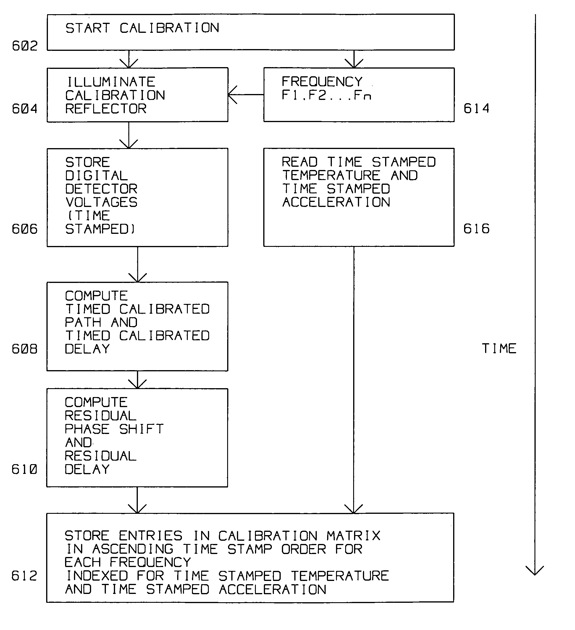
[0018]This disclosure introduces the concept of calibrating and distributing a single LADAR local oscillator signal to a plurality of (optical) lenses and associated detectors to facilitate parallel operation of the plurality of lenses for target detection and tracking within a volume.

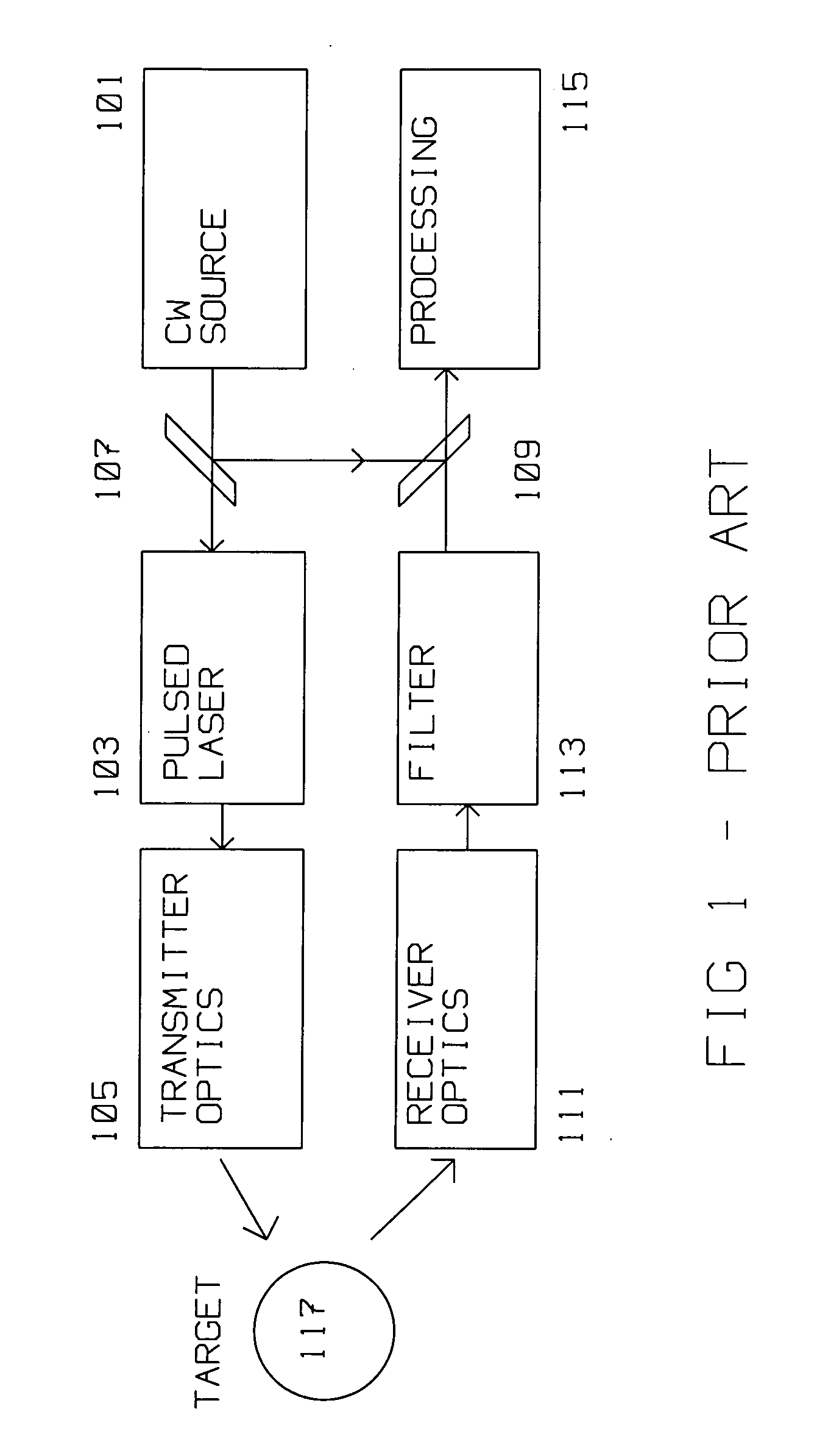
[0019]FIG. 1 shows the typical prior art LADAR heterodyne system. Continuous Wave (CW) Source 101 (a local oscillator), operating at a frequency, after passing through Beam Splitter 107, modulates Pulsed LASER 103 for amplification. The output from Pulsed LASER 103 is processed by Transmitter Optics 105 and directed to Target 117. Target 117 reflects part of the LASER energy from Transmitter Optics 105 to Receiver Optics 111. The output of receiver optics 111 is filtered for parameters of interest in filter 113.

[0020]A portion of CW Source 101 signal is routed by Beam Splitter 107 to Detector 109, a photo detector sensitive to energy from pulsed laser 103. Typically, CW Source 101 is adjusted to corres...


PUM


Abstract

A LADAR system for coherently imaging a target within a volume has a modulated laser transmitter at a frequency and a receiver. The receiver has a plurality of lenses, each with its own detector. Each detector is supplied by a centrally located local oscillator tuned to the frequency. The paths from the local oscillator to each detector, as well as the delay within each lens / detector combination are measured during a calibration. A calibrating reflector reflects a test signal during the calibration at many frequencies, temperatures and accelerations. Measurements of paths and delays obtained during the calibration are stored, and used to phase compensate subsequent target reflections for coherent processing.

Description

BACKGROUND OF THE INVENTION [0001]1. Field of Invention[0002]This disclosure is in the field of Laser Radar coherent target detection and imaging.[0003]2. Description of the Related Art[0004]Laser Detection and Ranging (LADAR) uses phase coherent processing at light frequencies to acquire targets within its detection range. Typically, both the velocity and location of a target is the result of the detection process. The principles of LADAR are detailed in the prior art as exemplified by G. C. Bachman in Laser Radar Systems and Techniques Artech House, 1979, incorporated herein in its entirety by reference.[0005]LADAR operation is at optical frequencies. These are higher than RADAR microwave frequencies. Thus, compared to RADAR, LADAR uses different concepts, has a theoretical larger bandwidth and higher angular resolution. Operating at optical frequencies, orders of magnitude greater than microwaves, LADAR poses unique advantages and limitations.[0006]One aspect of the complexities ...

Claims


Application Information

Patent Timeline
Patent Type & Authority Applications(United States)
IPC IPC(8): G01C3/00G01S17/87G01S17/89
CPCG01S7/4811G01S7/4816G01S17/89G01S17/87G01S7/497
Inventor KRIKORIAN, KAPRIEL V.ROSEN, ROBERT A.GUBALA, MICHAEL
Owner RAYTHEON CO
Why Eureka
Try Eureka