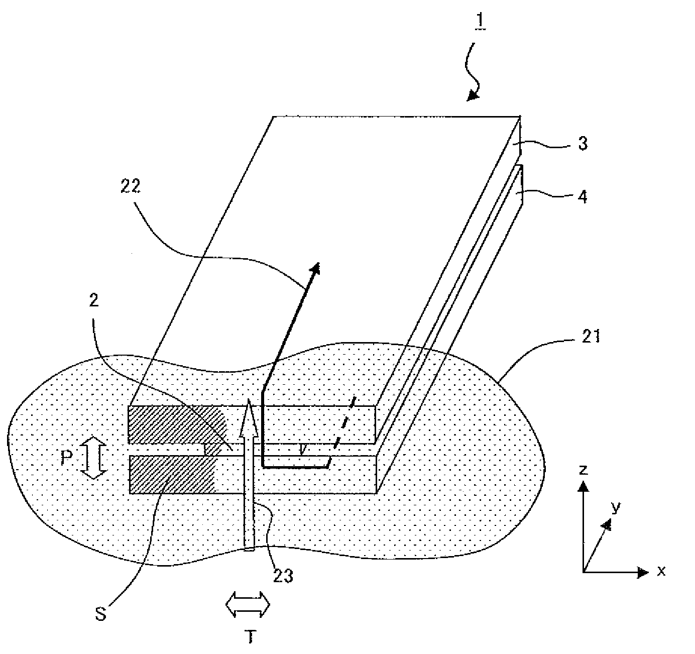
Cpp-type magnetoresistance effect element having three magnetic layers
a magnetoresistance effect and layer technology, applied in the field of element structure of a magnetoresistance effect element, can solve the problems of imposing limitation on a reduction in the thickness of the mr stack, the presence and the limited magnetization of the pinned layer as a whole, so as to improve the recoding density, simplify the layer configuration, and reduce the gap
- Summary
- Abstract
- Description
- Claims
- Application Information
AI Technical Summary
Benefits of technology
Problems solved by technology
Method used
Image

Examples
example 1
[0051]Next, the result of studying the magnetic thickness ratio between the above-described magnetic layers will be described.
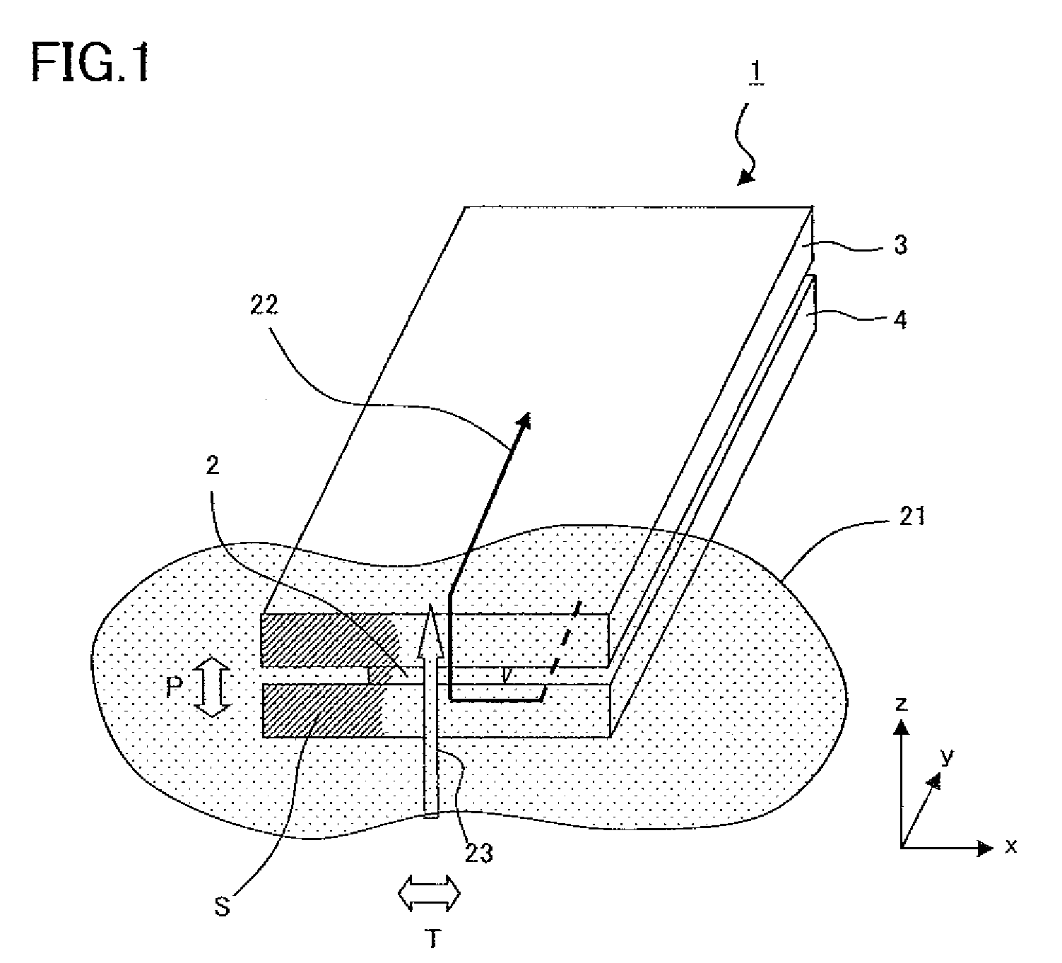
[0052]Several samples having the composition shown in Table 1 were prepared in which the thickness as a parameter in the shaded portions of the table was varied. The samples can be manufactured by a method described below. First, lower shield electrode layer 4 is prepared on a substrate. Next, each layer that constitutes MR stack 2 is formed on lower shield electrode layer 4 by means of sputtering. Next, the layers are formed into a shape by patterning, and portions on both sides with regard to track width direction T are filled with insulating films 16. Thereafter, by using milling, the MR stack is removed except for the portion whose height corresponds to the height of the element when measured from air bearing surface S, and then bias magnetic layer 14 is formed As a result of the above-mentioned steps, insulating films 16 are formed on both sides of MR st...
example 2
[0059]In example 2, in order to study the configuration of each of the magnetic layers, a number of samples with each magnetic layer having a multilayer structure of CoFe and CoFeB was prepared in which the thickness ratio therebetween in each magnetic layer was varied. The method of manufacturing the sample is as described above. An example of a layer configuration in example 2 is shown in Table 2. In Table 2, the numerical values in the row of “Composition” indicate the atomic fractions of the elements, and 80(90Co10Fe)20B indicates that the atomic composition ratio of “90Co10Fe” to “B” contained in CoFeB is 80:20.
TABLE 2Layer ConfigurationCompositionThickness (nm)Cap Layer 11Ta2.0Ru1.0Third Magnetic Layer 1080(90Co10Fe)20B2.990Co10Fe0.2Second Non-magnetic IntermediateMgO1.0Layer (Tunnel Barrier Layer) 9Second Magnetic Layer90Co10Fe0.6(Free layer) 880(90Co10Fe)20B1.0First Non-magnetic IntermediateRu0.8Layer 7First Magnetic Layer 690Co10Fe0.380(90Co10Fe)20B3.0Buffer Layer 5Ru2.0Ta2...
PUM
| Property | Measurement | Unit |
|---|---|---|
| thickness | aaaaa | aaaaa |
| thickness | aaaaa | aaaaa |
| thickness | aaaaa | aaaaa |
Abstract
Description
Claims
Application Information