Ups frequency converter and line conditioner

a frequency converter and converter technology, applied in the direction of power conversion systems, instruments, climate sustainability, etc., can solve the problems of inefficient operation, cost-intensive repair or replacement of electrical components, loss of productivity, etc., to improve converter operation, reduce or eliminate the effect of evaporation

Active Publication Date: 2009-09-24
SCHNEIDER ELECTRIC IT CORP
View PDF54 Cites 54 Cited by
  • Summary
  • Abstract
  • Description
  • Claims
  • Application Information

AI Technical Summary

Benefits of technology

[0007]Systems and methods disclosed herein monitor and control input to a converter in one or more of a UPS, a frequency converter, or a line conditioner. To increase efficiency, distortion due at least in part to ripple voltage can be removed from a control signal. Further, input current to the converter can be controlled. This improves converter operation and reduces or eliminates at least one of harmonic distortion and subharmonic oscillation signals from converter input. At least one aspect of the invention is directed to a method for controlling a converter. The method receives a voltage signal that includes distortion such as a ripple voltage and determines a control signal based in part on the voltage signal by comparing the voltage signal with a reference signal. The control signal can include distortion associated with the ripple voltage. The method produces an average control signal having less distortion than the control signal by filtering at least a portion of the ripple voltage from the control signal. The method generates a reference current value based at least in part on the average control signal and drives an input current of the converter toward the reference current value.

Problems solved by technology

Unwanted distortion in converter input current can pass through to converter output and be applied to electrical equipment, which results in inefficient operation, a loss of productivity, and can require costly repair or replacement of electrical components.

Method used


Image

  • Ups frequency converter and line conditioner
  • Ups frequency converter and line conditioner
  • Ups frequency converter and line conditioner

Examples


Embodiment Construction

[0023]This invention is not limited in its application to the details of construction and the arrangement of components set forth in the following description or illustrated in the drawings. The invention is capable of other embodiments and of being practiced or of being carried out in various ways. Also, the phraseology and terminology used herein is for the purpose of description and should not be regarded as limiting. The use of “including,”“comprising,” or “having,”“containing”, “involving”, and variations thereof herein, is meant to encompass the items listed thereafter and equivalents thereof as well as additional items.

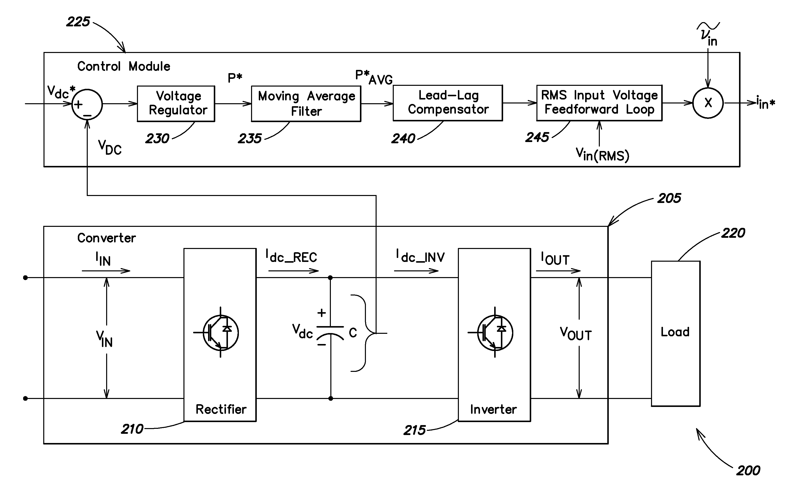
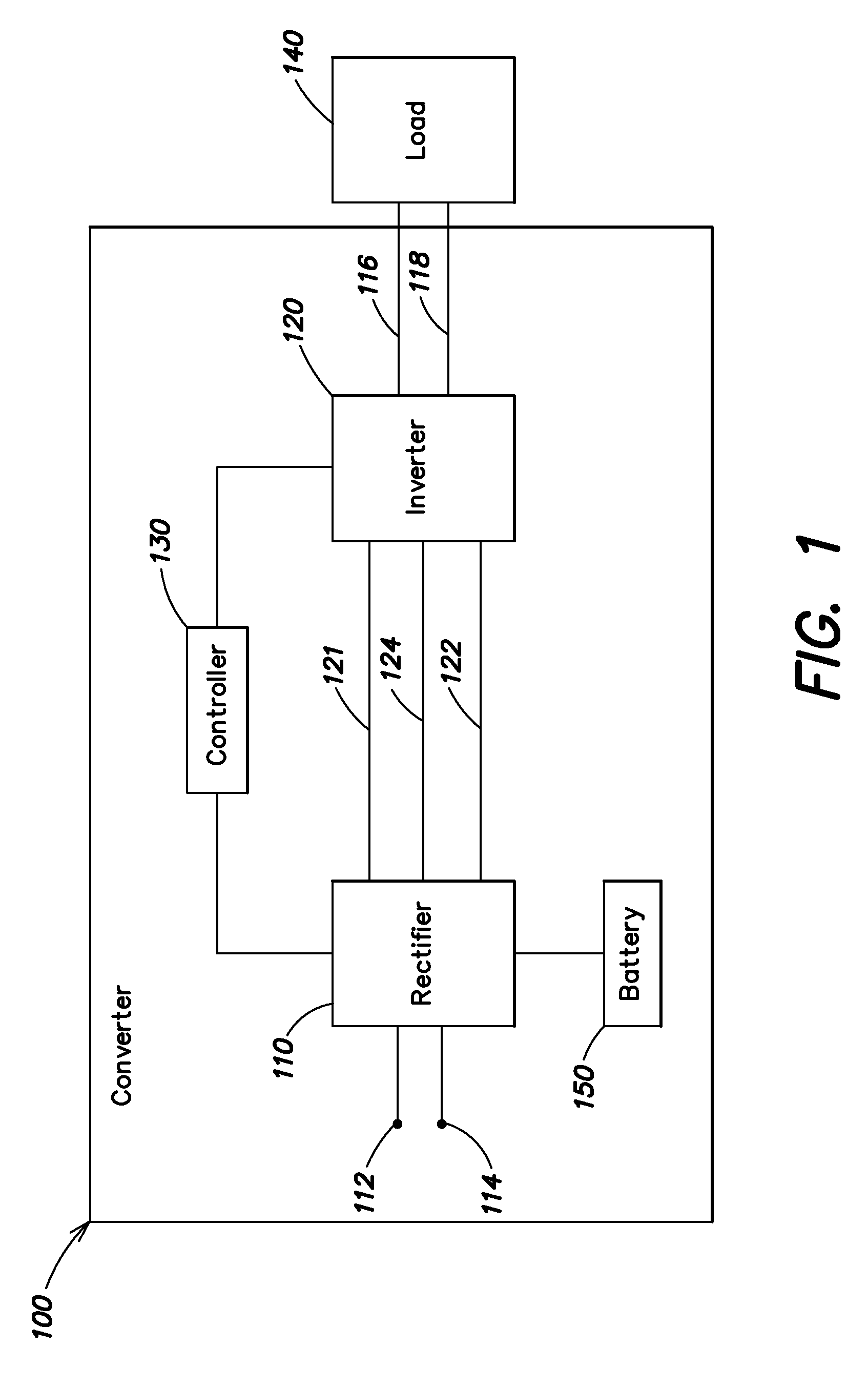
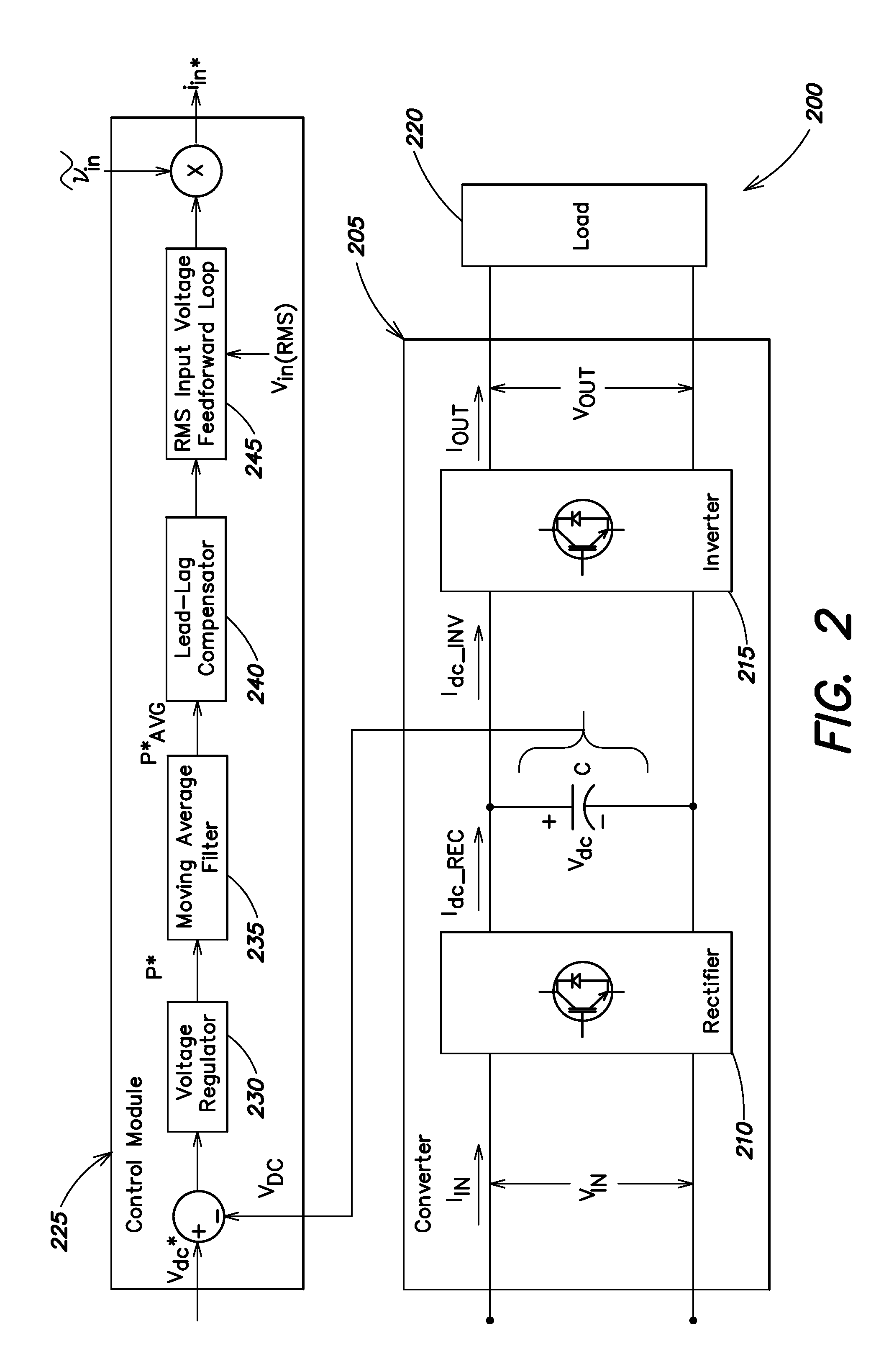
[0024]At least one embodiment of the present invention provides improved control of a converter, for example, in the converter of FIG. 1. However, embodiments of the present invention are not limited to the converter of FIG. 1, and may be used with other converters, power supplies, frequency converters, line conditioners, or other systems generally.

[0025]As sho...


PUM


Abstract

Systems and methods disclosed herein monitor and control input to a converter in one or more of a UPS, a frequency converter, or a line conditioner. Distortion due at least in part to ripple voltage can be removed from a control signal that controls input current to the converter. The systems and methods described herein afford a simple and effective way to reduce or eliminate one or more of subharmonic oscillation and total harmonic distortion from a converter input current during synchronous and asynchronous modes of operation. The converter may include one or more of a rectifier and an inverter.

Description

BACKGROUND OF THE INVENTION[0001]1. Field of the Invention[0002]At least one embodiment of the present invention relates generally to control of a converter, and more specifically, to control of a converter associated with at least one of an uninterruptable power supply, a frequency converter, and a line conditioner.[0003]2. Background of the Invention[0004]Converters that form at least part of uninterruptible power supplies (UPS), frequency converters, or line conditioners are used to provide reliable power to many different types of electronic equipment. Often, this electronic equipment requires particular voltage and / or current input from a converter. Unwanted distortion in converter input current can pass through to converter output and be applied to electrical equipment, which results in inefficient operation, a loss of productivity, and can require costly repair or replacement of electrical components.[0005]FIG. 1 provides a block diagram of a typical converter 100 that forms ...

Claims


Application Information

Patent Timeline
Patent Type & Authority Applications(United States)
IPC IPC(8): H02M1/12
CPCY02B70/126H02M1/4208Y02B70/10
Inventor PRASAD, PYBOYINAGHOSH, RAJESHKLIKIC, DAMIR
Owner SCHNEIDER ELECTRIC IT CORP
Why Eureka
Try Eureka