
Optical imaging apparatus and method for inspecting solar cells

a solar cell and optical imaging technology, applied in the direction of optical apparatus testing, instruments, structural/machine measurement, etc., can solve the problems of severe limitation of the power output of the solar cell, shortening or shunting, and the current optical inspection technology for the solar cell cannot meet the inspection requirements of high-quality manufacture in a mass-production line without increasing the budg

Inactive Publication Date: 2009-09-24
VISWELL TECH
View PDF6 Cites 48 Cited by
  • Summary
  • Abstract
  • Description
  • Claims
  • Application Information

AI Technical Summary

Benefits of technology

[0009]In one embodiment, the reverse biased voltage is the breakdown voltage of the p-n junctions of the solar cell. The temperatures of the hot spots are higher than a temperature threshold, and the sizes of the hot spots are larger than an area threshold.
[0010]The method for inspection of solar cells by an

Problems solved by technology

The current optical inspection technology for solar cells is not able to fulfill the inspection requirements for high quality manufacture in a mass-production line without increasing budget.
Defects or cracks in solar cells have the potential to severely limit the power output of a solar cell.
Significant defects or cracks may even cause shorts or shunts.
Current optical inspection apparatus may not be able to find all defects or cracks critical to solar cells in a mass production line, particularly those defects or cracks which are very small or hidden under the surface of the solar cells.

Method used


Image

  • Optical imaging apparatus and method for inspecting solar cells
  • Optical imaging apparatus and method for inspecting solar cells
  • Optical imaging apparatus and method for inspecting solar cells

Examples


Embodiment Construction

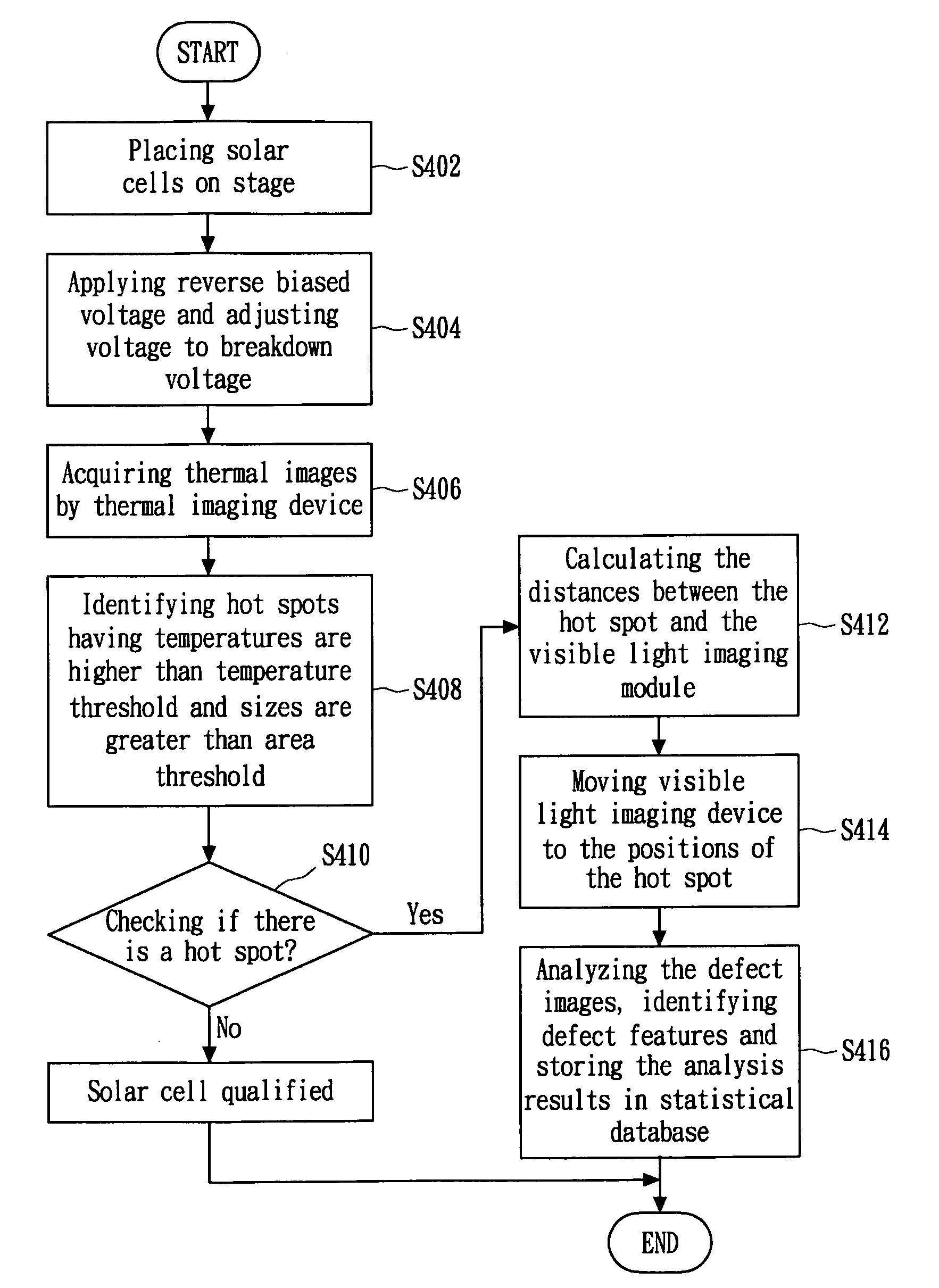
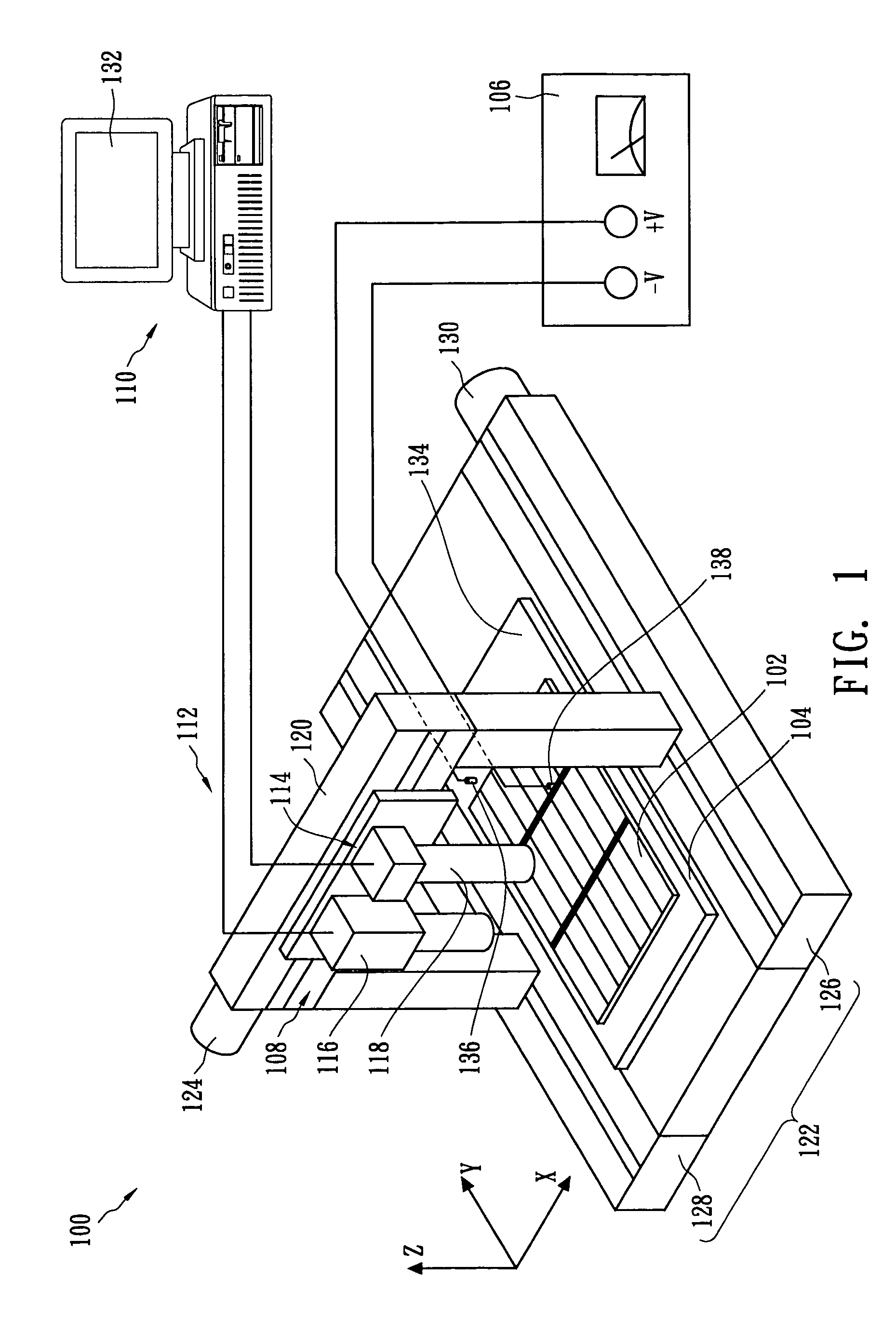
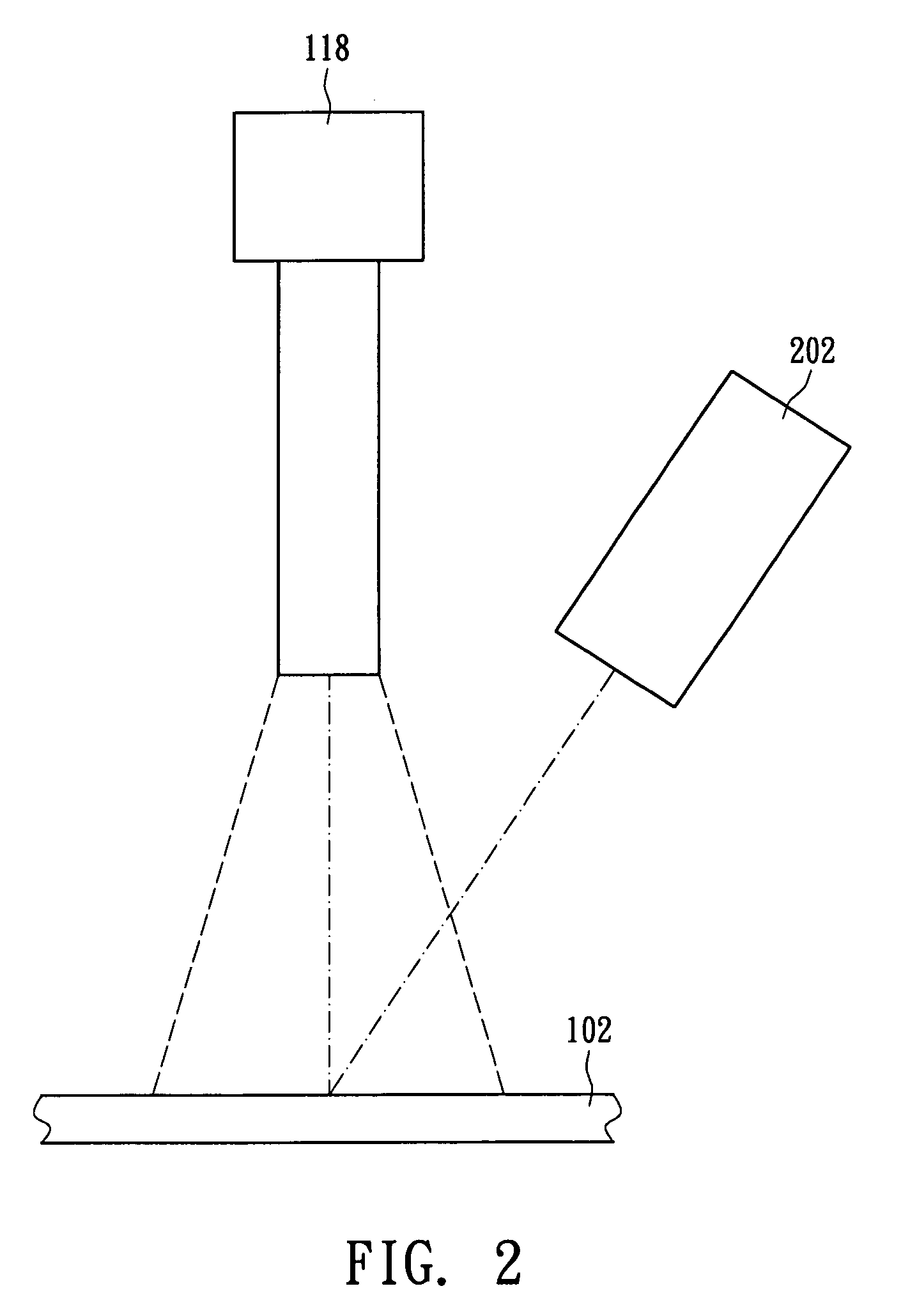
[0016]FIG. 1 and FIG. 2 illustrate an optical imaging apparatus 100 for inspecting a solar cell 102 according to one embodiment of the present invention. During inspection, the solar cell 102 is held and electrically coupled on the stage 104 of the optical imaging apparatus 100. A power supply 106 connected with the stage 104 and the solar cell 102 is used to provide a reverse-biased voltage to the solar cell 102 to increase its temperature. Some defects in the solar cell 102 generate heat locally under the reversed-biased voltage. A thermal imaging device 108, used to obtain the thermal images of the solar cell 102, includes an infrared camera 116, which is coupled to a computing unit 110. The computing unit 110 can extract, identify and locate the positions of the hot spots caused by defect heating effect. If there are hot spots, the computing unit 110 will also calculate the center positions of those hot spots.

[0017]Referring to FIG. 1, the stage 104 has a metal surface 134, whic...


PUM


Abstract

An optical imaging apparatus for inspecting a solar cell includes a power supply configured to apply a reverse biased voltage to the solar cell such that shunt defects in the solar cell will generate heat, a thermal imaging device configured to obtain the thermal image of the solar cell, a computing unit including a thermal image analysis module configured to identify hot spots in the thermal image, a locating module configured to locate the center positions of the hot spots, a visible image analysis module configured to identify the defect features of the hot spots, and a visible light imaging device configured to acquire visible images of the hot spots.

Description

BACKGROUND OF THE INVENTION[0001]1. Field of the Invention[0002]The present invention relates generally to an optical imaging apparatus and method for inspecting solar cells, and more particularly to an optical imaging apparatus and method for inspecting solar cells by thermal imaging biased solar cells and performing inspections of the defects by the visible imaging technique.[0003]2. Description of the Related Art[0004]Photovoltaic systems, such as conventional solar cells, directly convert sunlight into electrical energy using the principles of the photovoltaic conversion. The conversion efficiency has a direct influence on the output of electrical power, and it is also one of primary factors that determine the price of the solar cell. After manufacturing, solar cells will be tested to determine their conversion efficiency. Greater conversion efficiency results in higher selling prices. So, if a solar cell manufacturer wants to attain the most economical production, the manufactu...

Claims


Application Information

Patent Timeline
IPC IPC(8): G06K9/00
CPCG01M11/00G01M99/002H02S50/10H01L21/67271H01L31/18G01R31/311Y02E10/50
Inventor SU, CHIA HOLIN, WEN SHENGCHEN, KUANG YU
Owner VISWELL TECH
Features
  • Generate Ideas
  • Intellectual Property
  • Life Sciences
  • Materials
  • Tech Scout
  • Unparalleled Data Quality
  • Higher Quality Content
  • 60% Fewer Hallucinations
Learn More