Method for mixing liquids and liquid mixing apparatus

a technology of liquid mixing and mixing method, which is applied in the direction of liquid-liquid reaction process, solvent extraction, separation process, etc., can solve the problems of fine particles clogging the flow passage, difficult fabrication process, and large pressure loss of the flow passag

Active Publication Date: 2009-09-24
FUJIFILM CORP
View PDF8 Cites 21 Cited by
  • Summary
  • Abstract
  • Description
  • Claims
  • Application Information

AI Technical Summary

Benefits of technology

[0023]In the liquid mixing apparatus of the present invention, because a place where the liquids are made to join each other is on the rotational stage, fine particles formed by mixing never clog the flow passage. Accordingly, the liquid mixing apparatus can be used effectively.
[0024]According to the present invention, after discharging the plurality of liquids from a central portion of a rotational stage onto the rotational stage, allowing the liquids to form a thin layer by spreading the reaction liquids from the central portion to an outer peripheral portion side with a centrifugal force induced by a rotation of the rotational stage. At the same time, each reaction liquid is allowed to form a thin layer and further, to mix each other by diffusing it in an instant. Further, without making the liquids each other among the flow passage as was proceeded in the conventional apparatus, the mixture liquid neither contacts with a wall surface of the flow passage nor stay in the flow passage. Also, even when the fine particles generate, they never clog the flow passage and the liquids are made to mix each other efficiently.

Problems solved by technology

However, when the width of the flow passage is narrowed, although the diffusion time is reduced, the following problems occurred on the other hand: namely, the fabrication process is difficult, the pressure loss of the flow passage becomes too great, and when the fine particles are generated by diffusive mixing, the fine particles clog the flow passage.

Method used


Image

  • Method for mixing liquids and liquid mixing apparatus
  • Method for mixing liquids and liquid mixing apparatus
  • Method for mixing liquids and liquid mixing apparatus

Examples


examples

1. Mixing of Two Liquids

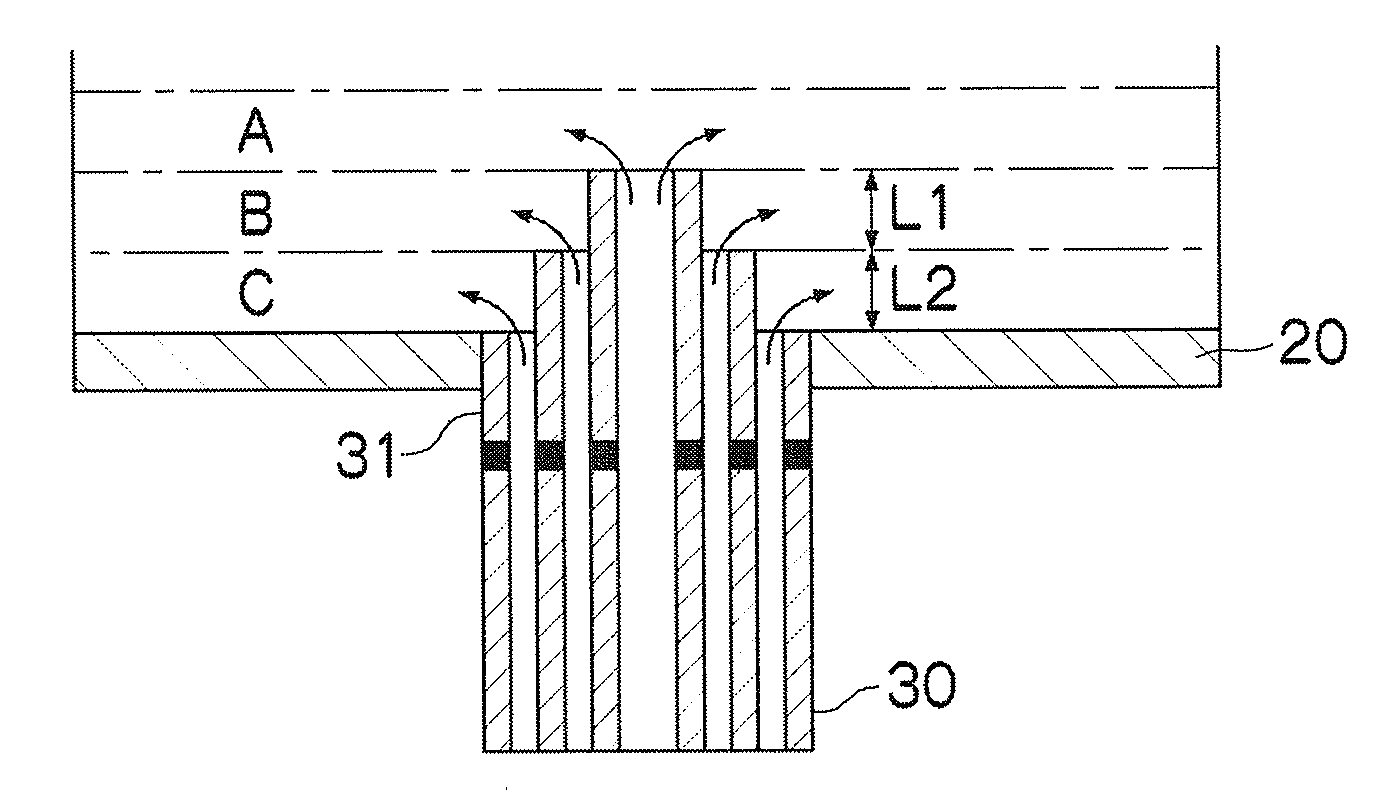
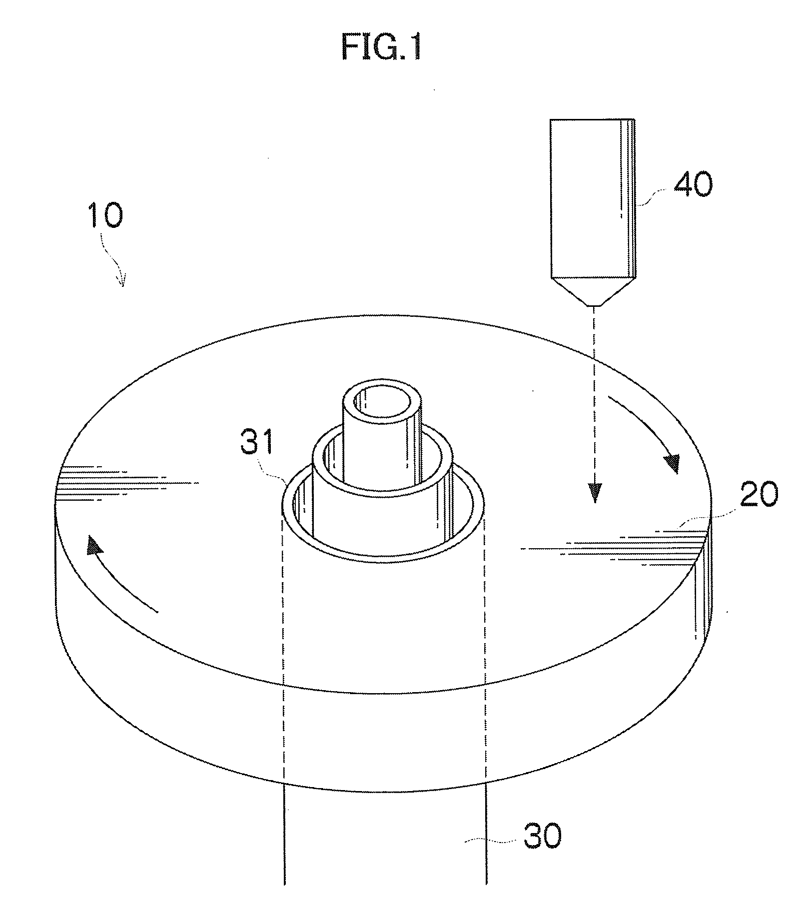
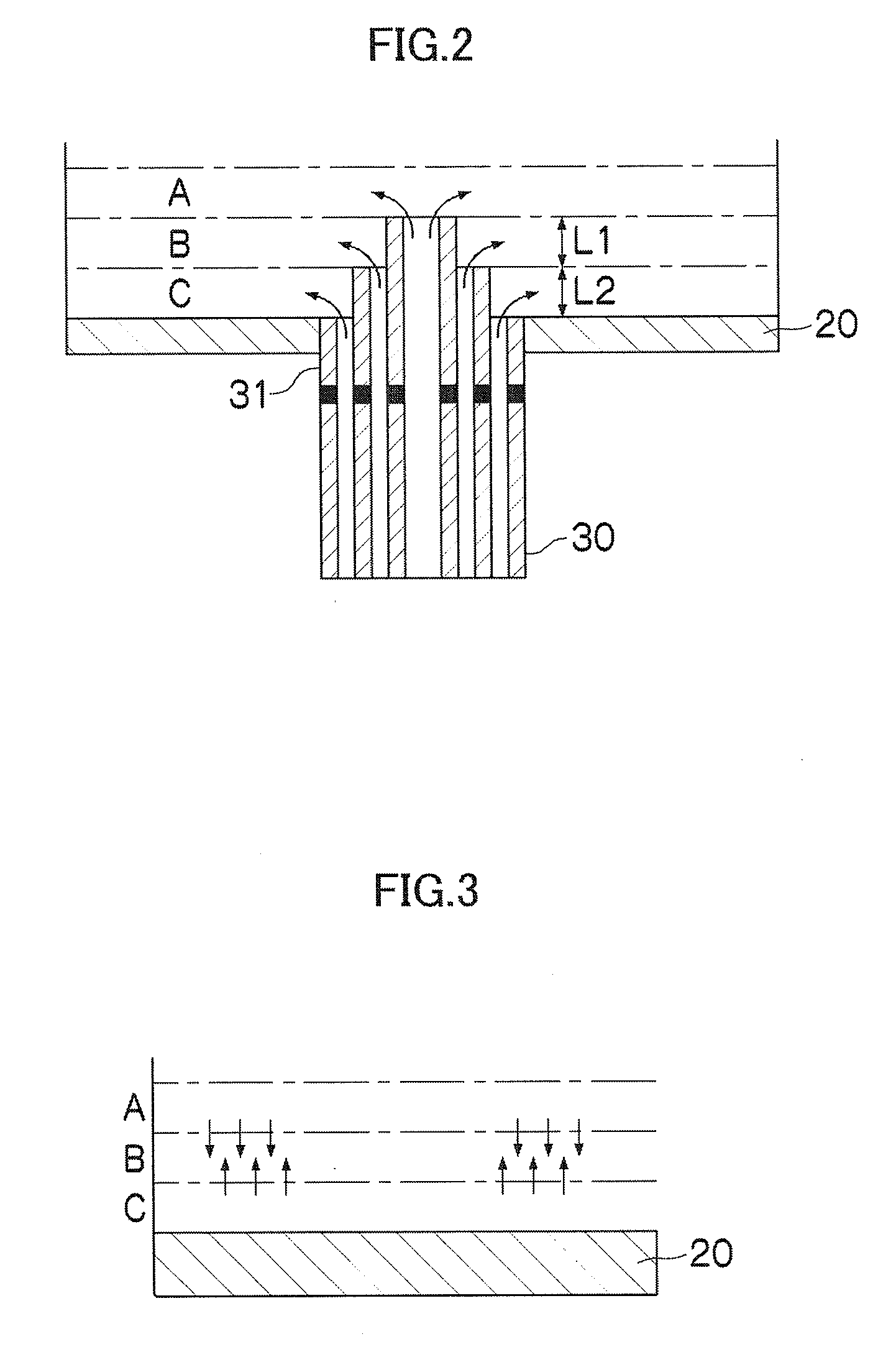
[0069]Using a flow passage having a multilayered cylindrical structure with two layers, two liquids are allowed to mix each other. An acidic aqueous solution (colorless) of pH-value 8 containing phenolphthalein pH indicator and alkaline aqueous solution of pH-value 12 were used. Flowing an acidic aqueous solution from the center of the nozzle, and flowing an alkaline aqueous solution from outside of the nozzle, a laminated body with the acidic aqueous solution as the first layer and the alkaline aqueous solution as the second layer was formed over the rotational stage. Then, the two liquids were allowed to mix each other in an instant. The flow rate was similarly 5 ml / min both about the acidic aqueous solution and the alkaline aqueous solution respectively. Further, the diameter of the center of the nozzle was 2 mm, and the diameter of the concentric circle was 3 mm. The number of revolutions of the rotational stage was 4,000 rpm. The resultant solution after...


PUM


Abstract

According to the method of an aspect of the present invention, by forming the laminated body of the liquids by laminating a plurality of liquids after discharging the plurality of liquids from a central portion of the rotational stage onto the rotational stage and rotating the rotational stage after the formation, the centrifugal force by the rotation enables the laminated body to form a thin layer. Accordingly, because the diffusion between the layers can be executed rapidly in the latter mixing process, a mixing of liquids is allowed to advance immediately.

Description

BACKGROUND OF THE INVENTION[0001]1. Field of the Invention[0002]The present invention relates to a method for mixing liquids, and a liquid mixing apparatus. More particularly, it relates to a method and an apparatus for allowing liquids to mix each other by their diffusion after forming a laminated structure of the liquids in the states of thin layers.[0003]2. Description of the Relate Art[0004]As one apparatus for mixing plural kinds of fluid effectively, for example, Japanese Patent Application Publication No. 2005-77219 proposes a microdevice which joins the plural kinds of fluid to flow together into an inlet of a microflow passage being a flow passage of a micron order, and enables to homogeneously mix them each other in an instant. As shown in FIG. 4, the microdevice is formed as a Y-shaped flow passage composed of a micro flow passage 114 which allows a plurality of fluids F1 and F2 to flow as a wafer-shaped laminar flow and causes them to mix each other or to react each othe...

Claims


Application Information

Patent Timeline
Patent Type & Authority Applications(United States)
IPC IPC(8): B01J4/00B01J14/00B01F15/02B01F15/00B01F25/74
CPCB01F5/221B01J14/00B01J2219/00891B01J19/1887B01J2219/00889B01J19/0093B01F25/741
Inventor TAKAHASHI, KAZUNORI
Owner FUJIFILM CORP
Why Eureka
Try Eureka