Control device for continuously variable transmission and control method thereof

a control device and transmission technology, applied in mechanical equipment, instruments, gearing, etc., can solve problems such as inability to realize learning corrections, and achieve the effect of suppressing the delay in clutch engagement or the shock of clutch engagement caused by rapid engagemen

Inactive Publication Date: 2009-09-24
JATCO LTD
View PDF4 Cites 3 Cited by
  • Summary
  • Abstract
  • Description
  • Claims
  • Application Information

AI Technical Summary

Benefits of technology

[0009]According to this invention, an oil pressure correction value can be learned even when a sensor for detecting the input side rotation speed of the clutch is not provided, and therefore, when the forward clutch or the reverse clutch is engaged, delays in clutch engagement or engagement shock caused by rapid engagement can be suppressed.

Problems solved by technology

Hence, when this sensor is not provided, the learning correction cannot be realized.

Method used


Image

  • Control device for continuously variable transmission and control method thereof
  • Control device for continuously variable transmission and control method thereof
  • Control device for continuously variable transmission and control method thereof

Examples


first embodiment

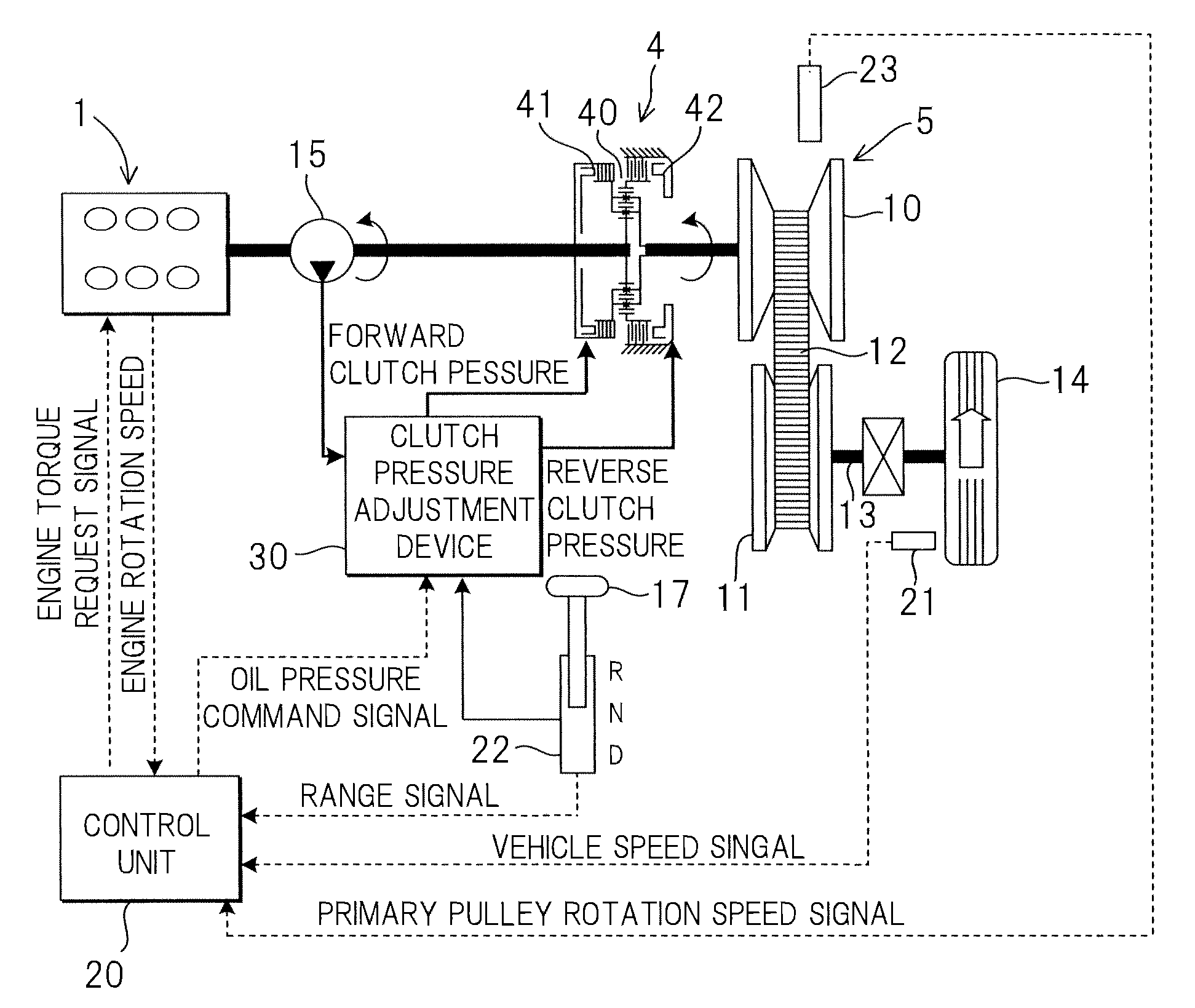
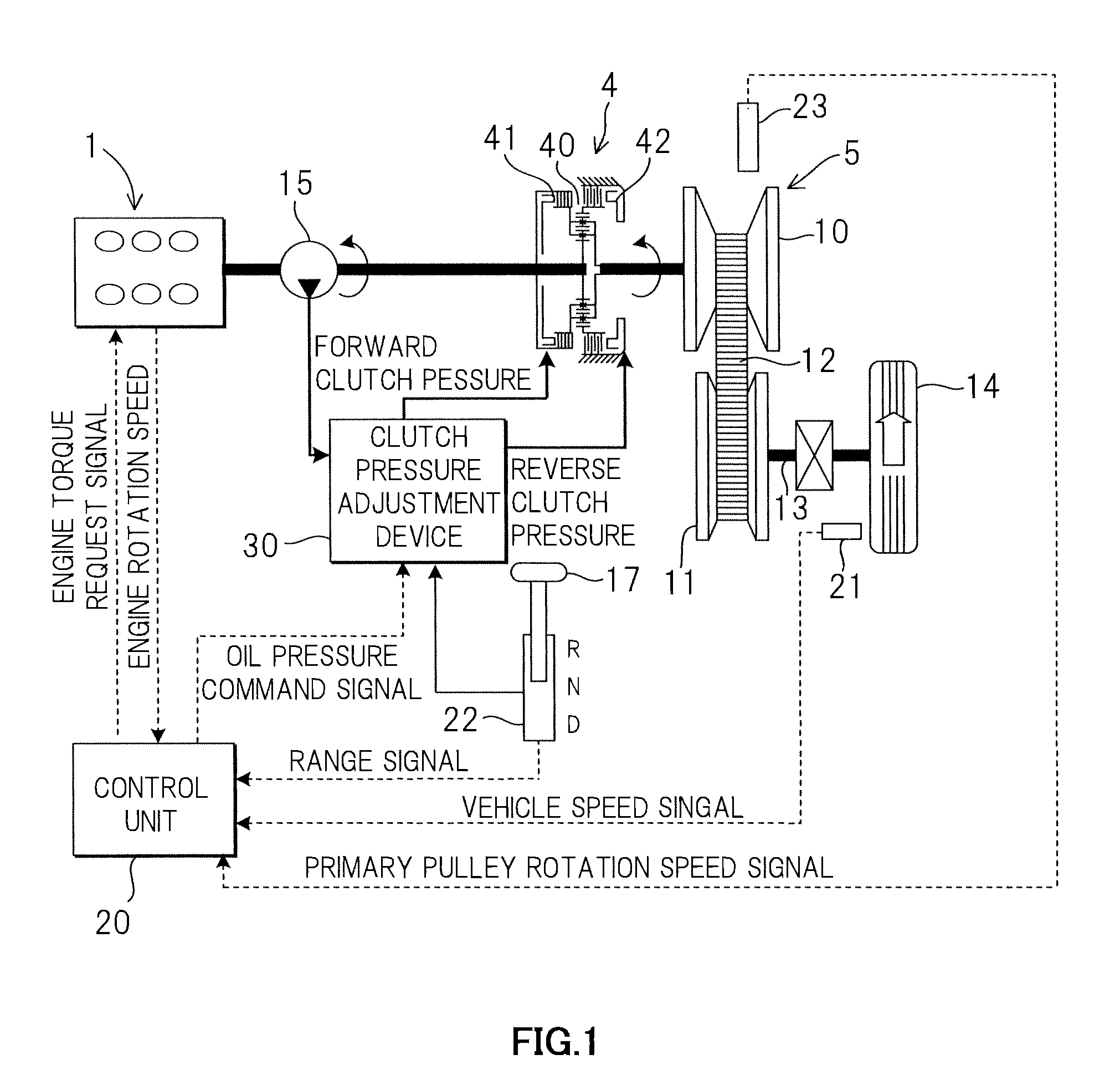
[0018]A power train according to this invention will be described below using the schematic diagram shown in FIG. 1.

[0019]In FIG. 1, the power train is mainly constituted by a forward-reverse switching mechanism 4 connected to an engine 1, and a continuously variable transmission 5 connected to an output shaft of the forward-reverse switching mechanism 4. The continuously variable transmission 5 comprises an input shaft side primary pulley 10 and a secondary pulley 11 connected to an output shaft 13, which together form a pair of variable pulleys, and the pair of variable pulleys 10, 11 are connected by a V belt (belt) 12. The output shaft 13 is connected to a drive shaft 14 via an idler gear and a differential gear. Further, start-up elements (not shown) such as a torque converter are interposed between an input side of the forward-reverse switching mechanism 4 and the engine 1.

[0020]The forward-reverse switching mechanism 4 is constituted by a planetary gear 40 that switches a pow...

second embodiment

[0114]Next, this invention will be described.

[0115]In this embodiment, a part of the method of setting the learned correction amount P_offset differs from that of the first embodiment, but all other constitutions and control are identical to the first embodiment, and therefore description thereof has been omitted.

[0116]The method of setting the learned correction amount P_offset according to this embodiment will be described using the flowchart shown in FIG. 6.

[0117]Control performed from a step S201 to a step S207 is identical to the control of the steps S101 to S107 in FIG. 3, and therefore description thereof has been omitted.

[0118]In a step S208, the reference time t_pulse_ref is read from the ROM of the control unit 20.

[0119]Control performed from a step S209 to a step S211 is identical to the control of the steps S109 to S111 in FIG. 3, and therefore description thereof has been omitted.

[0120]In a step S212, the reference correction amount ΔP_offset is calculated on the basis ...


PUM


Abstract

When a shift lever is shifted from an N range to a D range and a predetermined learning condition is established, a learning timer tm_pulse up to a point at which a pulse signal is detected by a primary pulley rotation speed sensor is calculated, and when a deviation between the learning timer tm_pulse and a reference correction amount ΔP_offset is larger than a predetermined threshold Δt_pulse_dif, a learned correction amount P_offset is updated.

Description

FIELD OF THE INVENTION[0001]This invention relates to a control device for a continuously variable transmission.BACKGROUND OF THE INVENTION[0002]In a conventional continuously variable transmission, when a driver switches a shift lever from an N range to a D range (or an R range) during start-up, the resulting motion is transmitted to a manual valve by a physical interlocking mechanism, and by displacing the manual valve to a position in which a clutch source pressure communicates with a piston oil chamber of a forward clutch (or a position in which the clutch source pressure communicates with a piston oil chamber of a reverse clutch (brake)), the forward clutch (or reverse clutch) is engaged such that engine torque is transmitted to the continuously variable transmission.[0003]When the shift lever is switched from the N range to the D range (or the R range), engagement of the forward clutch (or reverse clutch) is completed in three main phases, namely a pre-charging phase, an engag...

Claims


Application Information

Patent Timeline
Patent Type & Authority Applications(United States)
IPC IPC(8): F16H61/662G06F7/00G06F19/00F16H9/00F16H59/08F16H59/42F16H61/04F16H61/66
CPCF16D48/066F16D2500/1026F16D2500/1088F16D2500/3024F16D2500/31466F16D2500/3166F16H2342/04F16D2500/70605F16H61/0437F16H2061/0087F16H2061/0488F16H2061/661F16D2500/50251F16H59/36F16H61/04F16H61/66
Inventor SHINOHARA, FUMITONAM, JUHYUNDOIHARA, KATSUMISASAKI, HIDEAKIASAI, NORIOTANAKA, HIROYASUWAKAYAMA, HIDESHIKANEDA, TAKESHIAOKI, DAISUKE
Owner JATCO LTD
Why Eureka
Try Eureka