Electrical system testing using a wireless-controlled load bank

a wireless control and load bank technology, applied in the direction of engine testing, structural/machine measurement, instruments, etc., can solve the problems of not ensuring the best accuracy of such an evaluation, switching various devices on and off, and not providing a load range that will enable the full load rating of the alternator to be tested

Inactive Publication Date: 2009-10-01
INT TRUCK INTPROP LLC
View PDF10 Cites 5 Cited by
  • Summary
  • Abstract
  • Description
  • Claims
  • Application Information

AI Technical Summary

Benefits of technology

[0015]A generic aspect of the present invention relates to a method for testing an electrical system of motor vehicle comprising a powerplant in which fuel is combusted to generate heat for operating the powerplant to enable the powerplant to propel the vehicle and to operate electrical equipment in the electrical system that includes an alternator for generating electricity to maintain a desired state-of-charge of a D.C. battery bank that comprises one or more D.C. batteries.
[0016]The method comprises: connecting a test load bank to positive and negative terminals of one of the battery bank and the alternator; connecting a service tool for performing the test to the electrical system; disconnecting all electrical equipment from the battery bank except equipment required for operating the powerplant and maintaining battery bank state-of-charge; operating the powerplant; operating the service tool to perform the test; and during the test, wirelessly operating the load bank to change the load that the battery bank imposes on...

Problems solved by technology

The inventor has observed that the use of existing electrical devices in a motor vehicle to load the vehicle's electrical system for the purpose of evaluating the charging system may not assure the best accuracy of such an evaluation.
Switching various devices on and off may not provide a...

Method used


Image

  • Electrical system testing using a wireless-controlled load bank
  • Electrical system testing using a wireless-controlled load bank
  • Electrical system testing using a wireless-controlled load bank

Examples


Embodiment Construction

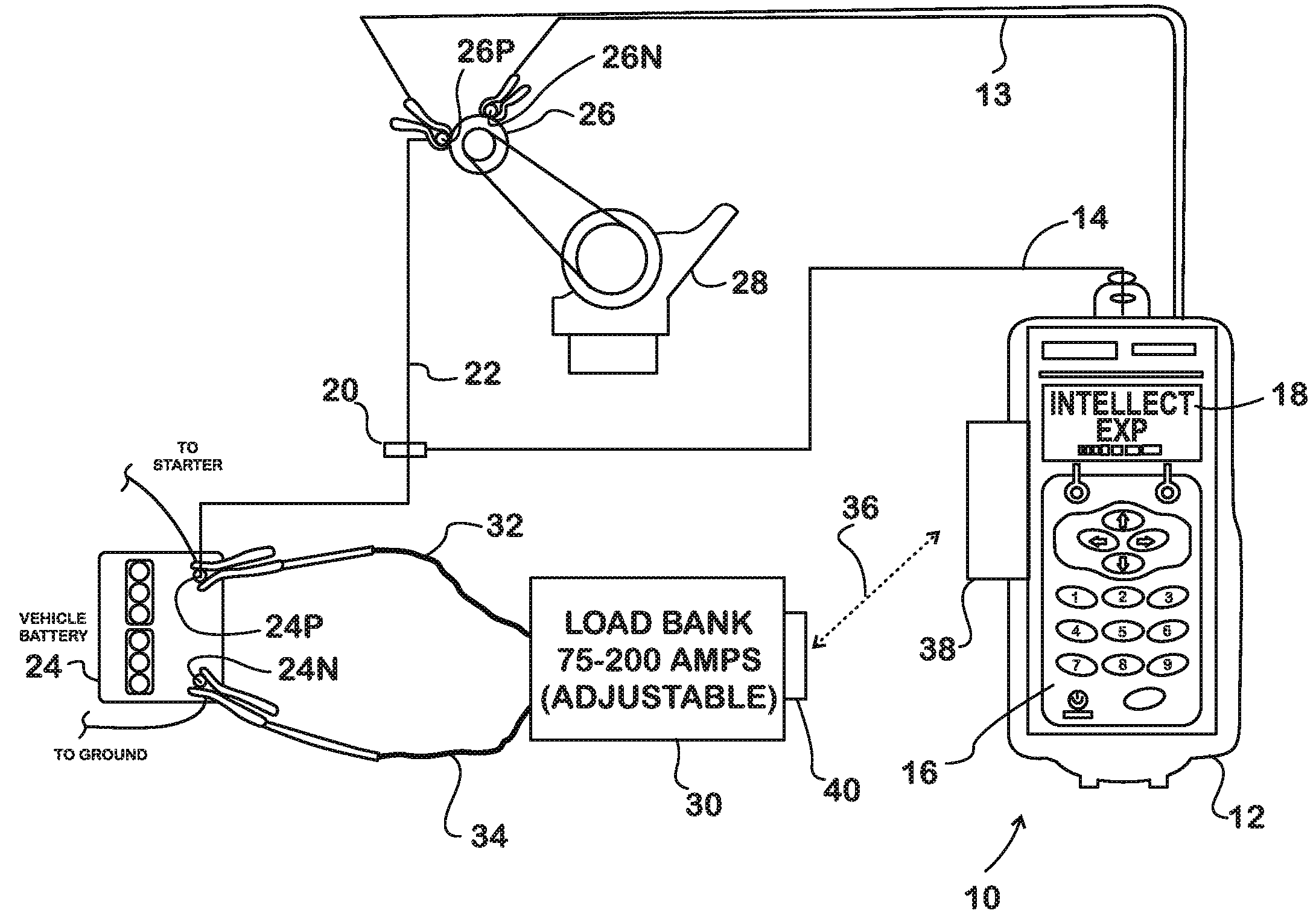
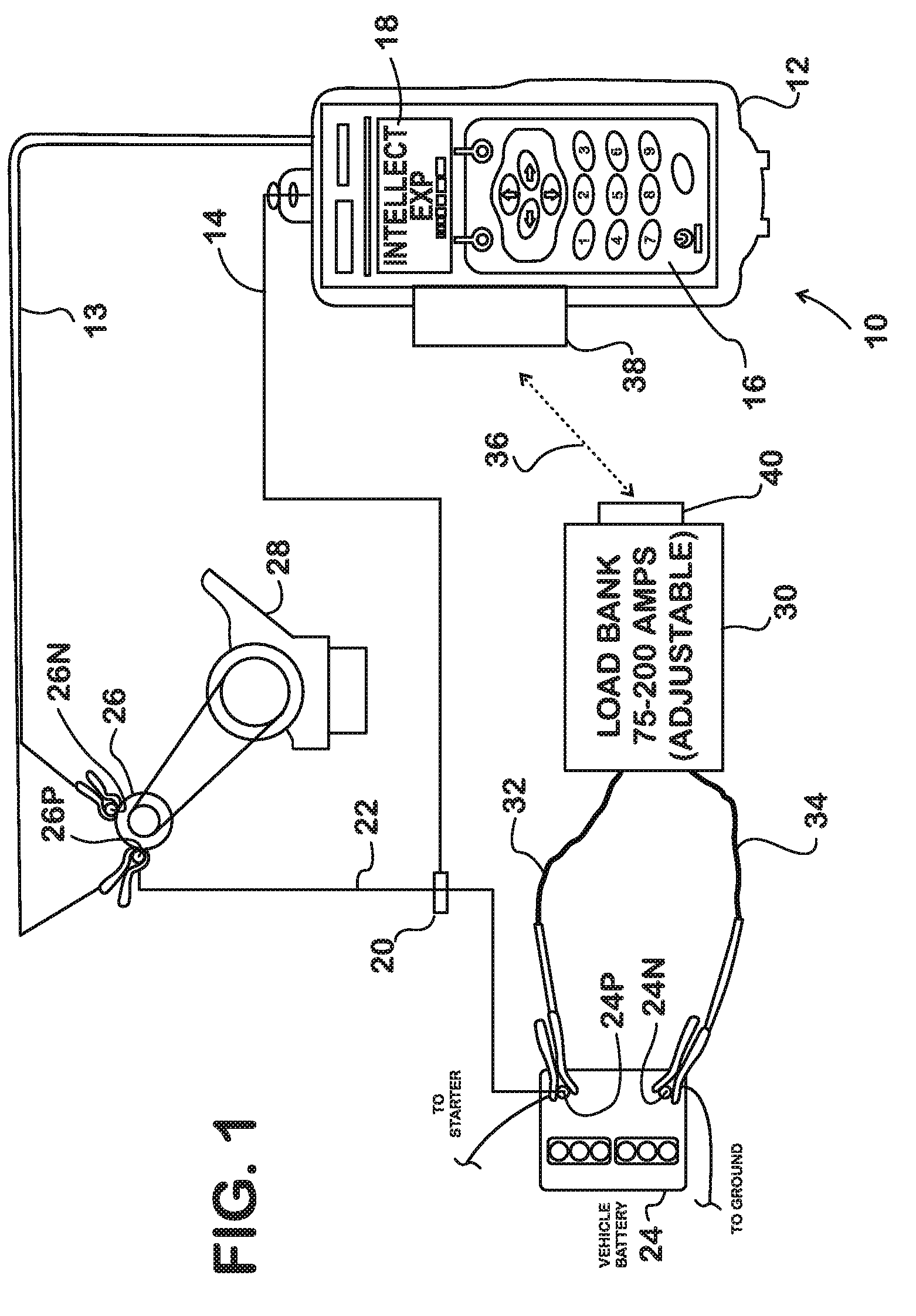
[0023]FIG. 1 shows a diagnostic test device 10, the “INTELLECT EXPHD” by way of example, for testing the electrical system in a motor vehicle. Device 10 comprises a handheld unit 12 and various test cables for connecting the unit to various portions of the electrical system to enable a technician to perform various diagnostic tests. Unit 12 has two ports, one of which provides for connection of a battery test cable 13 to the unit, and the other of which provides for connection of an accessory cable 14 to the unit. For performing a test and presenting test result data, unit 12 device comprises a keypad 16 and a display 18.

[0024]One of the accessories of cable 14 is an AMP CLAMP like the one described earlier. It comprises an electrical coil 20 that is shown clamped around the exterior of one or more wires or cables 22 that connect the positive terminal 24P of a bank of one or more D.C. storage batteries 24 and the positive output terminal 26P of an alternator that is operated by an i...


PUM


Abstract

A method for testing a circuit of a D.C. electrical system in a motor vehicle that includes connecting a load bank (30) to a D.C. electrical source such as a battery bank (24) or an alternator (26) and wirelessly operating the load bank (36) to set the load that the load bank imposes on the D.C. source during circuit testing.

Description

FIELD OF THE INVENTION[0001]This invention relates generally to diagnostic testing of motor vehicle electrical systems, particularly diagnostic testing that uses a load bank to test various circuits such as a battery charging circuit.BACKGROUND OF THE INVENTION[0002]Most motor vehicles have powerplants in which fuel is combusted to generate heat for operating the powerplant. Typical powerplants are internal combustion engines, either spark-ignition (gasoline) or compression-ignition (diesel). A running engine also operates various accessory devices like an alternator, air conditioner compressor, power steering pump, etc.[0003]An alternator generates electricity that supplies the needs of the vehicle electrical system including maintaining state-of-charge of a battery bank that comprises one or more D.C. storage batteries.[0004]Diagnostic testing of the various portions of the electrical system, such as the charging system, may be performed on occasion to assure that they are operati...

Claims


Application Information

Patent Timeline
IPC IPC(8): G01M15/04
CPCG01R31/007
Inventor EHLERS, MARK S.
Owner INT TRUCK INTPROP LLC
Why Eureka
Try Eureka