Variable valve gear for an internal combustion engine

a technology of internal combustion engine and variable valve gear, which is applied in the direction of valve details, valve arrangements, valve drives, etc., can solve the problems of end of bearing portion, abnormal abrasion, and abnormal abrasion, and achieve the effect of simple structur

Inactive Publication Date: 2009-10-01
MITSUBISHI MOTORS CORP
View PDF1 Cites 22 Cited by
  • Summary
  • Abstract
  • Description
  • Claims
  • Application Information

AI Technical Summary

Benefits of technology

[0014]The present invention has been made in light of the foregoing issues. It is an object of the invention to provide a variable valve gear for an internal combustion engine, which restricts a bearing portion from ...

Problems solved by technology

Furthermore, the displacement causes abnormal abrasion.
For this reason, if the end of the bearing portion, albeit slightly, projects from between the eccentric shaft and the harmonic ring, there generates such abnormal abrasion that the end of the bearing portion and the corner of the end face of the boss interfere with each other when the boss passes the end of the bearing portion.
In the case of the press fitting, however, it is difficult to reliab...

Method used


Image

  • Variable valve gear for an internal combustion engine
  • Variable valve gear for an internal combustion engine
  • Variable valve gear for an internal combustion engine

Examples


Embodiment Construction

[0029]The present invention will be described below with reference to one embodiment shown in FIGS. 1 to 6.

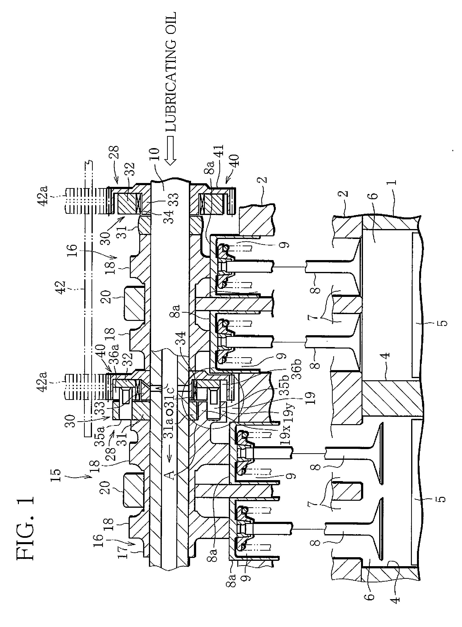
[0030]FIG. 1 is a cross-sectional view showing an internal combustion engine in which a variable valve gear is installed, for example, in an intake-side valve operating system of the engine. Reference mark 1 in FIG. 1 represents a cylinder block of the internal combustion engine, for example, a cylinder block (shown only in FIG. 1) of a 4-cylinder reciprocal gasoline engine (hereinafter, referred to as engine). Reference mark 2 denotes a cylinder head mounted on a head of the cylinder block 1.

[0031]First, the basic configuration of the engine will be explained. In the cylinder block 1, there are formed four cylinders 4 (FIG. 1 shows only some of the cylinders) to be serially arranged in an anteroposterior direction of the engine. A piston 5 is reciprocatably accommodated in each of the cylinders 4. Although not shown, the piston 5 is connected to a crankshaft through a connecti...


PUM


Abstract

The variable valve gear for an internal combustion engine includes a cam lobe that is rotatably supported by a cam drive shaft, and a variable valve mechanism that includes a drive arm fixed adjacent to one end of the cam lobe in the cam drive shaft, an eccentric shaft member that is swivelably supported at a position opposite to the cam lobe with respect to the drive arm in the cam drive shaft, has an outer circumferential surface eccentric to an axis of the cam drive shaft, and is adjustable in eccentricity, and an intermediate rotary member that is rotatably supported through a bearing member around the eccentric shaft member, and is connected to the drive arm, wherein the drive arm includes an end face that overlaps with an end face of the bearing member, when projecting along the axis of the cam drive shaft, and the end face of the drive arm is protruding further than the end face of the cam lobe toward the bearing member.

Description

BACKGROUND OF THE INVENTION[0001]1. Field of the Invention[0002]The present invention relates to a variable valve gear for an internal combustion engine, which varies the open period of a valve.[0003]2. Description of the Related Art[0004]Regarding a reciprocating engine (internal combustion engine) installed in an automobile, a variable valve gear has been developed, which varies a valve-open period according to the operational state of the engine in order to properly control the valve characteristics of intake and exhaust valves.[0005]Many variable valve gears of this type have a configuration in which a cam lobe that is rotatably fitted onto the outer circumferential surface of a camshaft (cam drive shaft) supported by a cylinder head is combined with a valve-open-period variable mechanism that varies the rotational velocity of the camshaft at predetermined cycles to transmit the rotation to the cam lobe, as disclosed in Japanese Patent Gazette (Laid pen No. 10-280925). A lot of ...

Claims


Application Information

Patent Timeline
IPC IPC(8): F01L1/34
CPCF01L1/356F01L1/34
Inventor HOSHIKAWA, JUNHIGASHI, HIROFUMIFUJIMOTO, AKIBIROOHSAWA, NORITSUGUTATSUMI, TETSUJIMURAOKA, TOMOYUKINAKAI, HIDEO
Owner MITSUBISHI MOTORS CORP
Why Eureka
Try Eureka