Crankcase structure for an overhead-camshaft internal combustion engine, and engine incorporating same

a technology of camshaft and crankcase, which is applied in the direction of machines/engines, valve drives, mechanical equipment, etc., can solve the problems of unfavorable weight increase, and achieve the effects of preventing chain dropping, high stiffness, and light weigh

Active Publication Date: 2009-10-01
HONDA MOTOR CO LTD
View PDF0 Cites 7 Cited by
  • Summary
  • Abstract
  • Description
  • Claims
  • Application Information

AI Technical Summary

Benefits of technology

[0014]An ordinary internal combustion engine is rarely operated in the condition where the cylinder(s) is directed down or skewly down. In the present invention according to the first aspect therefore, the extremely highly stiff loop guide-engaging recess disposed at a position on a surface passing through the center of the crankshaft and substantially orthogonal to the cylinder center line is not adjacent to that minimum-radius starting end of the opening surface of the crankcase at which stress concentration is liable to occur. Therefore, such configuration makes it possible to avoid stress concentration in the vicinity of the loop guide-engaging recess which is extremely high in stiffness.
[0015]In addition, the loop-retaining member is located in the vicinity of a position just under the crankshaft, and is adjacent to the small-radius starting end of the inner peripheral surface of the opening of the crankcase. Therefore, the loop-retaining member for preventing the dropping of the timing endless chain wrapped around the loop drive sprocket fitted over the crankshaft protruding from the opening can be brought close to the loop drive sprocket. Accordingly, the dropping of the chain can be prevented securely.
[0016]Further, of the inner peripheral surface of the opening of the crankcase, the portion ranging from the loop guide-engaging recess to the terminal end part of ...

Problems solved by technology

In order to avoid this problem, the crankcase wall is made...

Method used


Image

  • Crankcase structure for an overhead-camshaft internal combustion engine, and engine incorporating same
  • Crankcase structure for an overhead-camshaft internal combustion engine, and engine incorporating same
  • Crankcase structure for an overhead-camshaft internal combustion engine, and engine incorporating same

Examples


Embodiment Construction

[0027]An embodiment of the present invention will now be described, with reference to the drawings. Throughout this description, relative terms like “upper”, “lower”, “above”, “below”, “front”, “back”, and the like are used in reference to a vantage point of an operator of the vehicle, seated on the driver's seat and facing forward. It should be understood that these terms are used for purposes of illustration, and are not intended to limit the invention.

[0028]Now, an illustrative embodiment of the present invention is described below with reference to FIGS. 1 to 7.

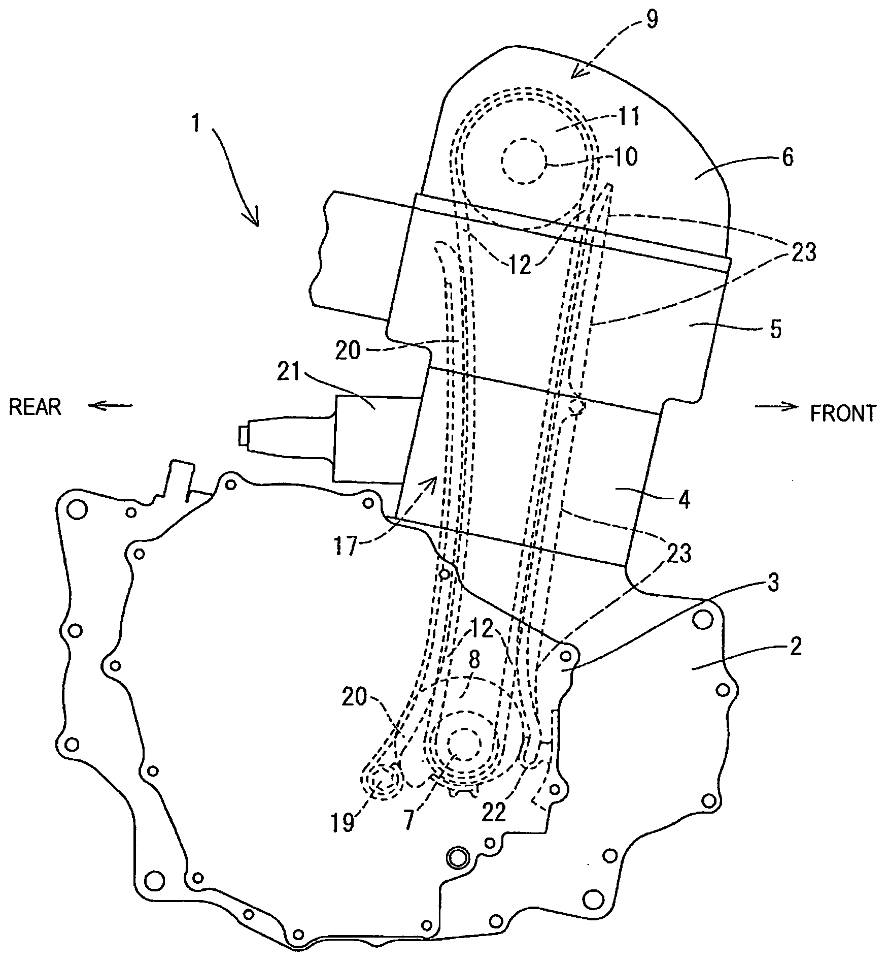
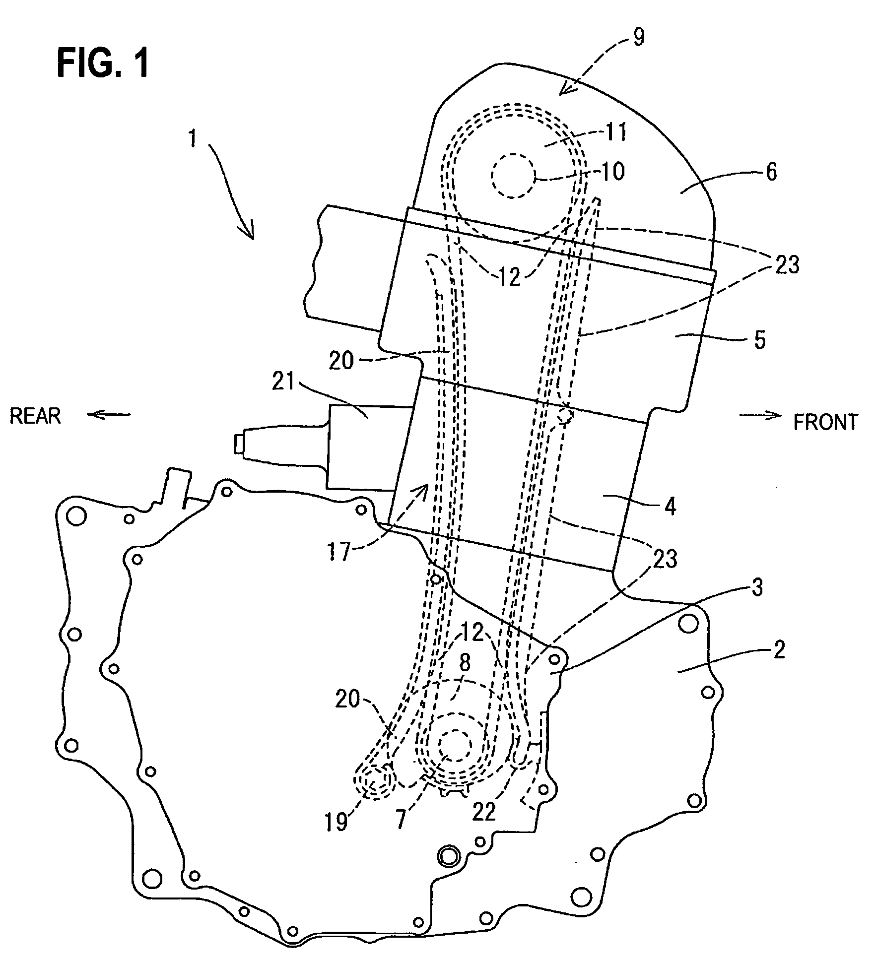
[0029]An OHC internal combustion engine 1 shown in FIG. 1 is a 4-stroke-cycle single-cylinder internal combustion engine mounted on a motorcycle (not shown). The engine 1 may be a multi-cylinder internal combustion engine. The OHC internal combustion engine 1 includes a left-right split type crankcase (in FIG. 1, only a right crankcase 2 is shown) and a crankcase cover detachably attached to an outside surface of the left...


PUM


Abstract

An overhead-camshaft internal combustion engine having an outer wall of a crankcase provided adjacent a crankshaft, with a spiral-surfaced opening through which the crankshaft is passed. The outer crankcase wall is integrally provided with a loop guide engaging recess formed thereon. The loop guide engaging recess supports a base end portion of a loop guide for guiding an endless chain. A loop-retaining member for preventing the timing endless chain from dropping is arranged at a position on the lower side of a loop drive sprocket integrally formed at an end portion of the crankshaft.

Description

CROSS-REFERENCE TO RELATED APPLICATIONS[0001]The present invention claims priority under 35 USC 119 based on Japanese patent application No. 2008-094134, filed on Mar. 31, 2008. The entire subject matter of this priority document, including specification claims and drawings, is incorporated by reference herein.BACKGROUND OF THE INVENTION[0002]1. Field of the Invention[0003]The present invention relates to a crankcase structure for an over head camshaft (OHC) type of internal combustion engine. More particularly, the present invention relates to a crankcase structure having a loop guide locking (engaging) recess and a loop-retaining member integrally formed on a crankcase of the OHC internal combustion engine.[0004]2. Description of the Background Art[0005]There is a known OHC internal combustion engine in which a loop guide engaging recess is formed at an outer periphery of a crankshaft-penetrated opening in a crankcase of the internal combustion engine, the crankshaft-penetrated op...

Claims


Application Information

Patent Timeline
IPC IPC(8): F02B77/00
CPCF01L1/024F02B67/06F02F7/0073F02F7/0068F02F7/0058
Inventor KURIBARA, HIROSHIKEYAKI, SHINICHIRONISHI, TORUIINO, KAZUAKI
Owner HONDA MOTOR CO LTD
Why Eureka
Try Eureka