Techniques for improved uniformity tuning in an ion implanter system

a technology of uniformity tuning and ion implanter, which is applied in the field of uniformity tuning in the ion implanter system, can solve the problems of inefficient and inefficient existing methods for tuning an ion implanter system, inability to achieve consistent ion beam output in an efficient manner, and inability to achieve uniformity tuning. improve the effect of uniformity tuning

Active Publication Date: 2009-10-01
VARIAN SEMICON EQUIP ASSOC INC
View PDF5 Cites 26 Cited by
  • Summary
  • Abstract
  • Description
  • Claims
  • Application Information

AI Technical Summary

Benefits of technology

[0013]Techniques for improved uniformity tuning in an ion implanter system are disclosed. In one particular exemplary embodiment, the techniques may be realized as a method for improved uniformity tuning in an ion implanter system. The method may comprise generating an ion beam in an ion implanter system. The method may also comprise measuring a first ion beam current density profile along an ion beam path. The method may further comprise measuring a second ion beam current density profile along the ion beam path. In addition, the method may comprise determining a third ion beam current density profile along the ion beam path based at least in part on the first ion beam current density profile and the second ion beam current density profile.

Problems solved by technology

It follows from these assumptions that, during scanning, the ion spot beam will only exhibit small changes and any resulting non-uniformity in current density distribution of the scanned ion beam along its beam path is also small.
However, due to a number of deficiencies, existing methods for tuning an ion implanter system often fail to achieve a consistent ion beam output in an efficient manner.
Thus, existing algorithms render ion implanter systems less efficient by increasing tuning time and thereby decreasing productivity.
However, identical ion beam currents do not necessarily guarantee identical ion beam conditions.
As a result, single-parameter approaches that rely solely on ion beam current can lead to inconsistent ion beam geometries.
Since a previously recorded single set of beam-line element settings often cannot reproduce a desired ion beam condition, an ion implanter system may have to be re-tuned for every wafer batch, which is quite time-consuming for reasons described below.
In view of the foregoing, it may be understood that there are significant problems and shortcomings associated with current ion implanter tuning technologies.

Method used


Image

  • Techniques for improved uniformity tuning in an ion implanter system
  • Techniques for improved uniformity tuning in an ion implanter system
  • Techniques for improved uniformity tuning in an ion implanter system

Examples


Embodiment Construction

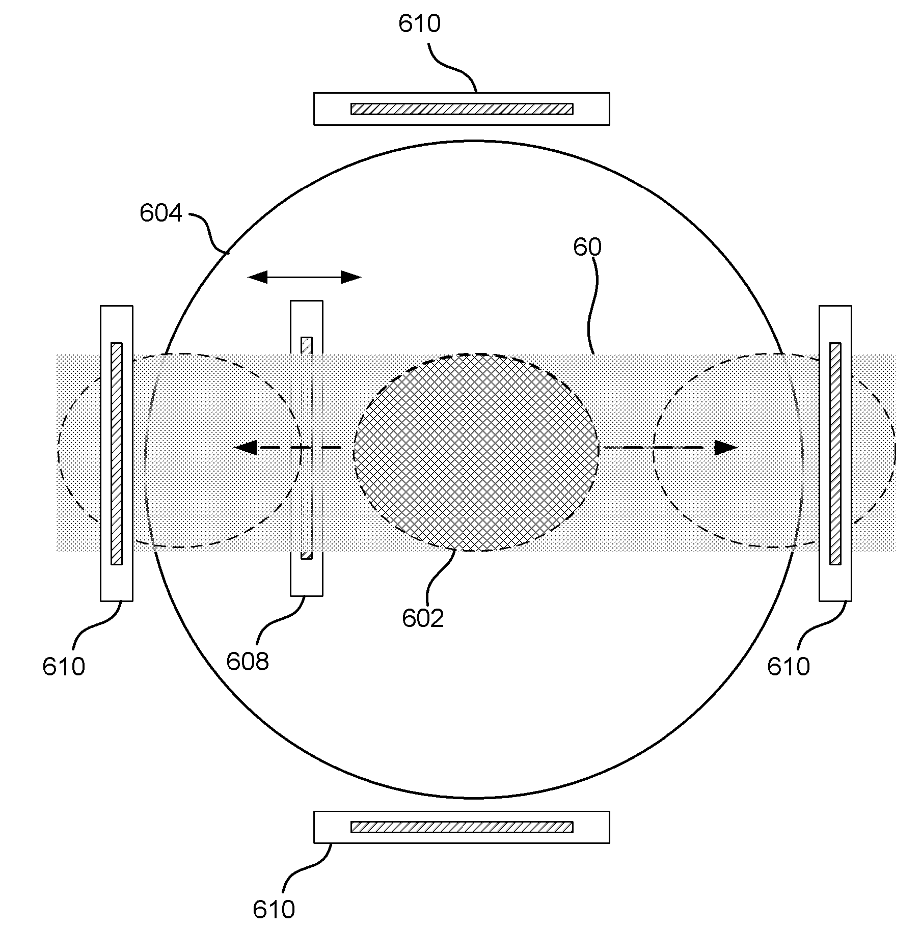
[0043]Embodiments of the present disclosure are directed to techniques for improved uniformity tuning in an ion implanter system. According to an improved method, an ion beam profile along a beam path can be precisely determined by measuring the ion beam at a plurality of predetermined locations. The measurements of the ion beam at the plurality of predetermined locations may be taken as function of one or more variables. Also, the measurements may be taken with either a stationary measurement device or a mobile measurement device. The ion beam profile may accurately capture all changes, large or small, in the ion beam during scanning. Based on this ion beam profile, a desired scan velocity profile may be generated to closely control scanning of the ion beam in order to achieve a more uniform ion beam profile. This improved method may reduce the number of iterations required for uniformity tuning of an ion implanter system and may introduce a confidence level in the uniformity tunin...


PUM


Abstract

Techniques for uniformity tuning in an ion implanter system are disclosed. In one particular exemplary embodiment, the techniques may be realized as a method for ion beam uniformity tuning. The method may comprise generating an ion beam in an ion implanter system. The method may also comprise measuring a first ion beam current density profile along an ion beam path. The method may further comprise measuring a second ion beam current density profile along the ion beam path. In addition, the method may comprise determining a third ion beam current density profile along the ion beam path based at least in part on the first ion beam current density profile and the second ion beam current density profile.

Description

FIELD OF THE DISCLOSURE[0001]The present disclosure relates generally t0 semiconductor equipment and, more particularly, to techniques for improved uniformity tuning in an ion implanter system.BACKGROUND OF THE DISCLOSURE[0002]Ion implantation is a process of depositing chemical species into a substrate by direct bombardment of the substrate with high-energy ions. In semiconductor fabrication, ion implanters are used primarily for doping processes that alter the type and level of conductivity of target materials. A precise doping profile in an integrated circuit (IC) substrate and its thin-film structure is often crucial for proper IC performance. To achieve a desired doping profile, one or more ion species may be implanted in different doses and at different energy levels. A specification of the ion species, doses and energies is often referred to as an ion implantation recipe.[0003]FIG. 1 depicts a conventional ion implanter system 100. As is typical for most ion implanter systems...

Claims


Application Information

Patent Timeline
Patent Type & Authority Applications(United States)
IPC IPC(8): H01J37/08
CPCH01J37/304H01J37/3171H01J2237/24542H01L21/265H01J2237/30483H01J2237/31703H01J2237/30455
Inventor EVANS, MORGAN D.
Owner VARIAN SEMICON EQUIP ASSOC INC
Why Eureka
Try Eureka