Track assembly having wear inhibiting contact members

a technology of contact members and track components, which is applied in the direction of driving chains, ring springs, vehicle cleaning, etc., can solve the problems of significant wear, wear and galling of seals and track pins, and the track components are subjected to substantial loads

Active Publication Date: 2009-10-01
CATERPILLAR INC
View PDF8 Cites 20 Cited by
  • Summary
  • Abstract
  • Description
  • Claims
  • Application Information

AI Technical Summary

Benefits of technology

[0007]One aspect of the present disclosure is directed to a track assembly for a machine. The track assembly may include a track having a first chain assembly and a second chain assembly coupled with the first chain assembly via a track pin, the first and second chain assemblies including an inner track link and an outer track link. The track assembly may also include a rotatable bushing positioned about the track pin, a sleeve bearing disposed within a first bore of the inner track link and positioned about the track pin, a first seal member disposed between the inner track link and the rotatable bushing, a second seal member disposed between the inner and outer track links, a first thrust ring positioned about the track pin and engaged with the rotatable bushing, a second thrust ring disposed about the track pin and engaged with the sleeve bearing, a first contact member engaged with the first seal member, and a second contact member engaged with the second seal member, the first and second contact members configured to inhibit wear of the first and second seal members.

Problems solved by technology

Over the course of many hours of operation, the constant contact among the moving track components may result in significant wear, even where bearings and lubricating oil are used to reduce friction among the components.
Galling and other wear related problems tend to be particularly prevalent with relatively large track-type machines, which may subject the track components to substantial loads.
In particular, wear and galling of the seals and the track pins are problematic.
Although the crawler device of the '491 patent may improve the durability of some components of the crawler device, it may have limitations.
For example, the first and second seals may still undergo wear even in the presence of lubricating oil.
Contact between the seals and the crawler links may eventually wear down the seals, resulting in costly repairs and replacements.

Method used


Image

  • Track assembly having wear inhibiting contact members
  • Track assembly having wear inhibiting contact members
  • Track assembly having wear inhibiting contact members

Examples


Embodiment Construction

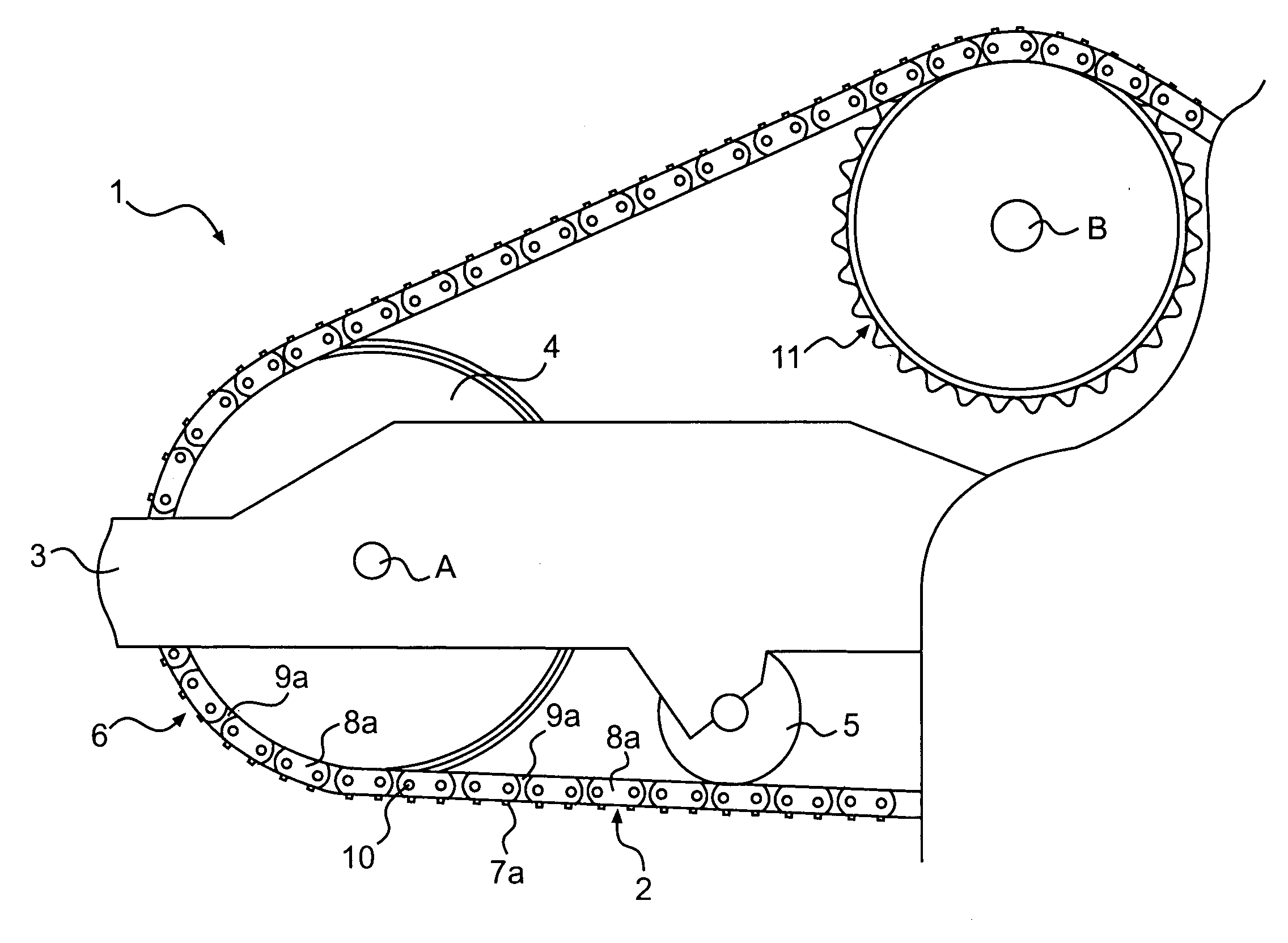
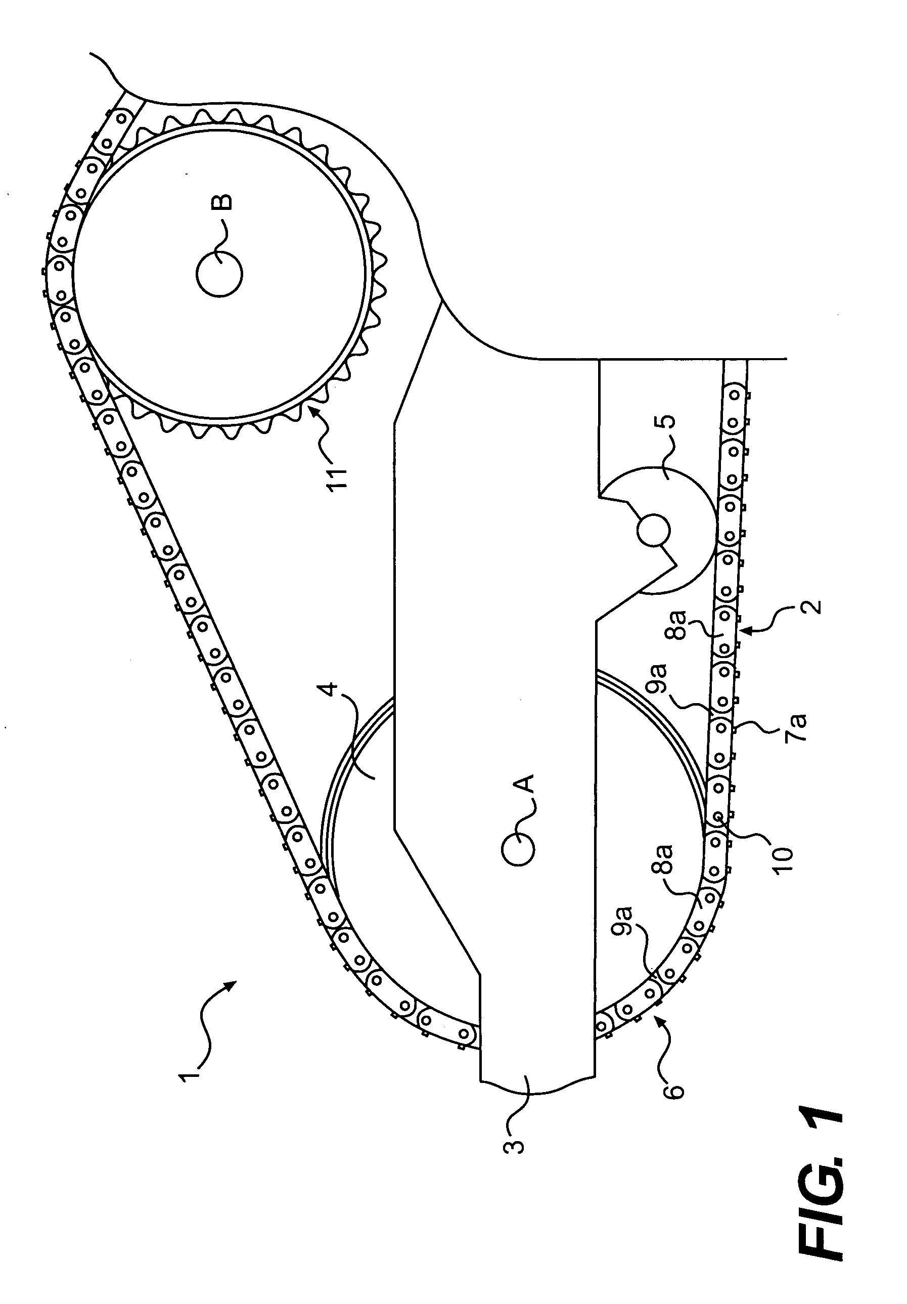
[0014]A portion of machine 1 according to the present disclosure is shown in FIG. 1. Machine 1 is shown in the context of a track-type machine having a ground engaging track 2, mounted at a first side of a frame 3, and also including a second ground engaging track identical to track 2 and positioned at a second side of frame 3 but not shown in FIG. 1. Track 2 extends about a plurality of rotatable track engaging elements, including an idler 4 having an axis of rotation A, a drive sprocket 11 having an axis of rotation B, and a plurality of track rollers 5. Machine 1 may also include other rotatable track engaging elements coupled with each of its one or more tracks, such as an additional idler. While only a single track is shown in FIG. 1, the present description of track 2 and track assembly 6 of which it is a part should be understood to refer also to a second track and associated track assembly 6 of machine 1. While machine 1 may be a track-type machine such as a track loader, an...


PUM


Abstract

A track assembly for a track-type machine is disclosed. The track assembly includes inner and outer track links. A rotatable bushing is positioned about a track pin and a sleeve bearing is positioned about the track pin. A first seal member is disposed between an inner track link and the rotatable bushing and a second seal member is disposed between inner and outer track links. A first thrust ring is engaged with the rotatable bushing and a second thrust ring is engaged with the sleeve bearing. A first contact member is engaged with the first seal member and a second contact member is engaged with the second seal member. The first and second contact members are configured to inhibit wear of the first and second seal members.

Description

TECHNICAL FIELD[0001]The present disclosure is directed to a track assembly, and more particularly, to a track assembly having wear inhibiting contact members.BACKGROUND[0002]Track-type or crawler-type machines may be employed in construction, mining, oil, gas, and forestry operations, and in other rugged operating environments. These machines employ tracks which engage the ground and enable the machine to move about and over relatively rough terrain. Typical track designs include a track pin, either rotatably engaged or fixed to a pair of track chain assemblies, and a bushing rotatably positioned between the track chain assemblies. The tracks may operate in adverse environments in which track joints may be exposed to various abrasive mixtures of water, dirt, sand, rock, and / or chemical elements and to wide temperature ranges varying from high heat in deserts to extreme cold in arctic regions. Seals may be placed in the track joints in a variety of configurations and positions to en...

Claims


Application Information

Patent Timeline
Patent Type & Authority Applications(United States)
IPC IPC(8): B62D55/20
CPCB62D55/0887B62D55/21B62D55/092
Inventor DIEKEVERS, MARK STEVENJOHANNSEN, ERIC JAMESLIVESAY, RICHARD EDWARDSTEINER, KEVIN LEE
Owner CATERPILLAR INC
Why Eureka
Try Eureka