Combination smoke and heat detector

a smoke detector and heat detector technology, applied in the direction of fire alarms, instruments, fire alarm radiation actuation, etc., can solve the problems of inconvenient use, increase in cost, and difficulty in capture of air (thermal currents), and achieve the effect of simple structur

Active Publication Date: 2009-10-01
NOHMI BOSAI LTD
View PDF5 Cites 10 Cited by
  • Summary
  • Abstract
  • Description
  • Claims
  • Application Information

AI Technical Summary

Benefits of technology

[0010]The present invention has been made for solving the above-mentioned problems, and it is therefore an object of the present invention to provide a combination

Problems solved by technology

Thus, there are problems of inconvenience and rise in cost due to increases in number of components and in structural complexity.
As a result, the direction in which the light can be visually confirmed is limited, which leads to inc

Method used


Image

  • Combination smoke and heat detector
  • Combination smoke and heat detector
  • Combination smoke and heat detector

Examples


Embodiment Construction

Embodiment: Combination Smoke and Heat Detector

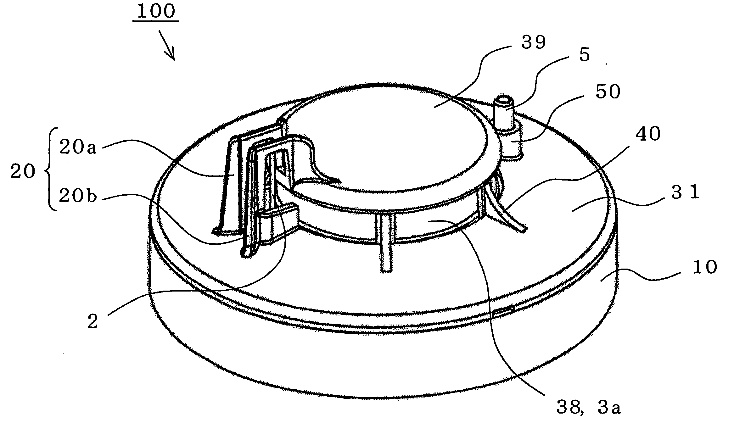
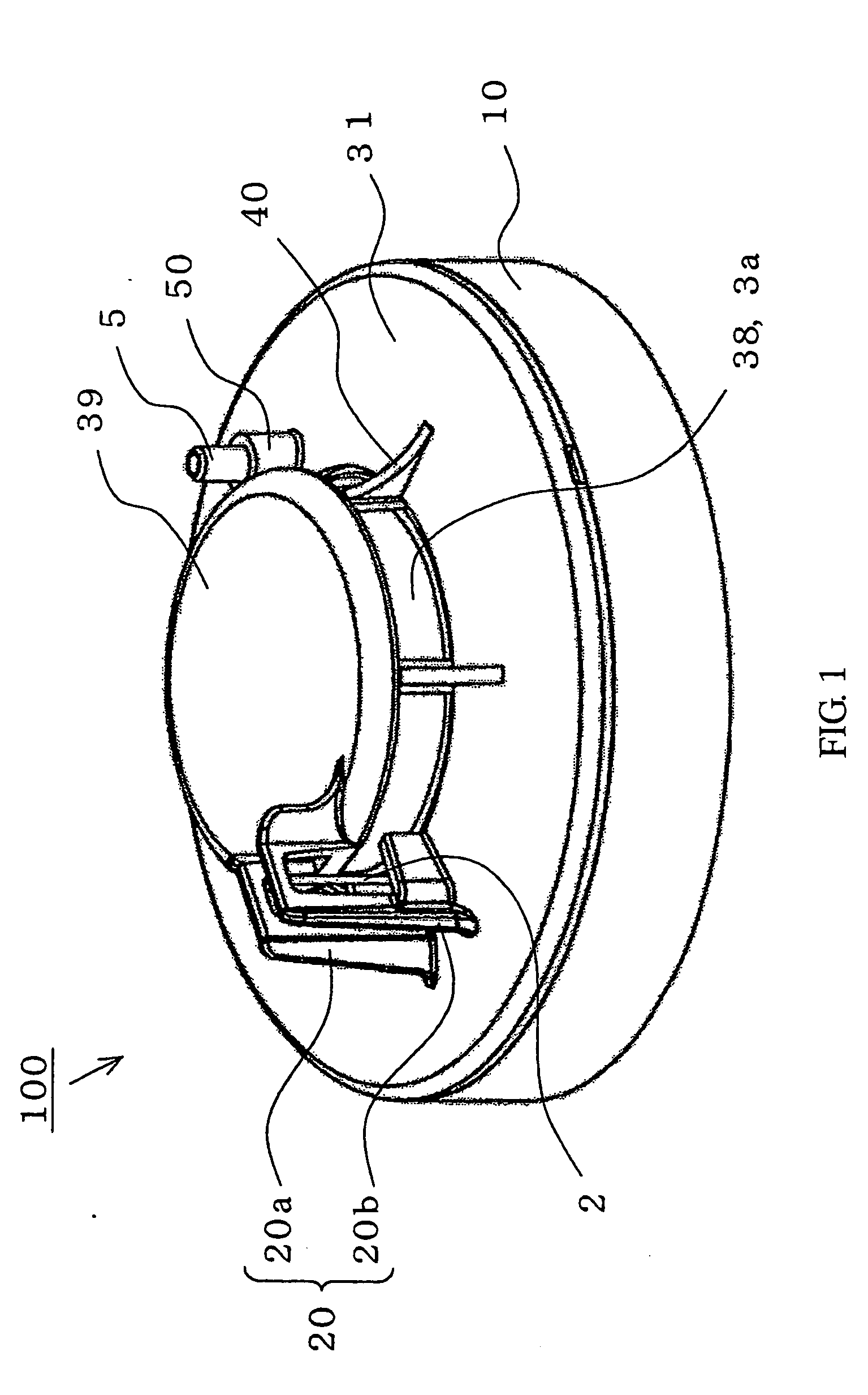
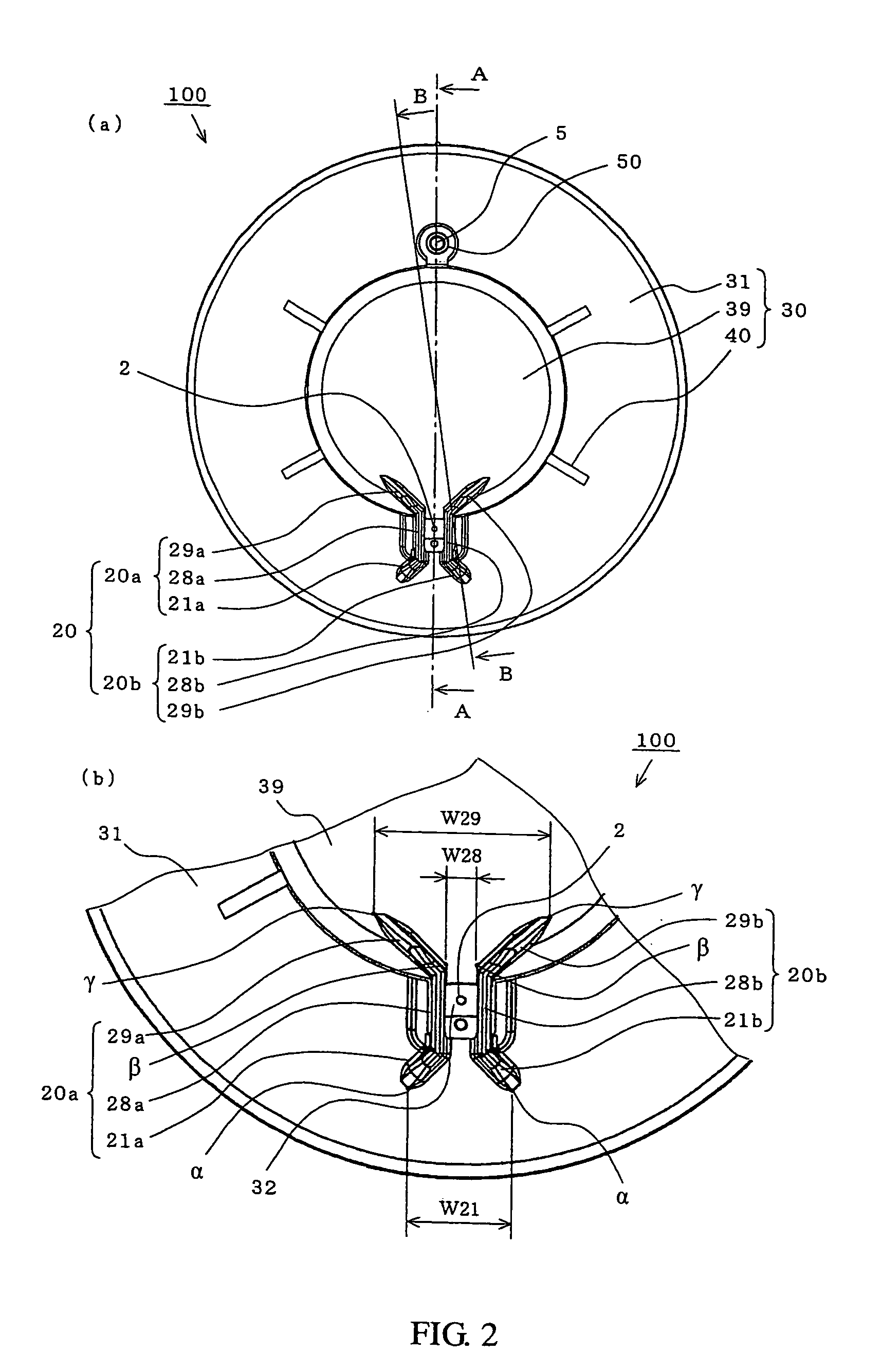
[0075]In the following, a combination smoke and heat detector according to an embodiment of the present invention is described with reference to drawings. Note that, in each of the drawings, the same portions are denoted by the same reference symbols, and a part of description is omitted.

[0076]FIGS. 1 to 9 illustrate a combination smoke and heat detector according to embodiments of the present invention. FIG. 1 is a perspective view illustrating the entire thereof. FIG. 2(a) is a plan view illustrating the entire thereof. FIG. 2(b) is a partially enlarged plan view thereof. FIG. 3 is a side view illustrating the entire thereof. FIG. 4 is a front view illustrating the entire thereof. FIG. 5 is a side sectional view illustrating the entire thereof. FIG. 6 is an enlarged sectional view of a part of FIG. 5. FIGS. 7(a) and 7(b) are side sectional views illustrating divided parts thereof. FIG. 8 is a substantially side-sectional view illustra...


PUM


Abstract

Provided is a combination smoke and heat detector which allows, in spite of a simple structure, light emitted from an indication lamp to be visually confirmed from a wide range of directions. A combination smoke and heat detector (100) includes a body base (10), a printed circuit board (1), a thermosensitive element (2), a dark chamber (3), an indication lamp (4) mounted to the printed circuit board (1), a protective cover (30), and a bar-like light guide (5) for guiding light emitted from the indication lamp (4) to outside of the protective cover (30). The light guide (5) passes through a light guide through-hole (35) formed in the protective cover (30) so as to be mounted therein, with one end surface thereof being faced with the indication lamp (4), and another end surface thereof protruding to the outside of the protective cover (30) by a height substantially equal to or larger than a protruding height of the dark chamber (3). Further, the light guide (5) is arranged oppositely to the thermosensitive element (2), with the dark chamber (3) being sandwiched therebetween.

Description

BACKGROUND OF THE INVENTION[0001]1. Field of the Invention[0002]The present invention relates to a combination smoke and heat detector.[0003]2. Description of the Related Art[0004]Conventionally, combination smoke and heat detector is normally installed to the indoor ceiling and the like, and include a temperature detection means for detecting air temperature, a smoke detection means for detecting smoke in the air, and a determination means for determining whether or not a fire occurs on the basis of detection results of those means. Further, the combination smoke and heat detector includes an “indication lamp” blinking for notifying that the combination smoke and heat detector is in a normal operational state, or lighting up for notifying that it is the combination smoke and heat detector which has detected the occurrence of a fire.[0005]In the combination smoke and heat detector, a printed circuit board which is provided with the determination means is mounted in a cylindrical bod...

Claims


Application Information

Patent Timeline
IPC IPC(8): G08B19/00G01K1/08
CPCG08B17/06G08B29/183G08B17/113G08B17/107
Inventor KATOU, TOMOHIROITOU, TAKASHIKATOU, KENICHI
Owner NOHMI BOSAI LTD
Why Eureka
Try Eureka