Imaging apparatus and lighting apparatus for imaging
- Summary
- Abstract
- Description
- Claims
- Application Information
AI Technical Summary
Benefits of technology
Problems solved by technology
Method used
Image

Examples
second embodiment
[0078]Another example for fulfilling the reflection on eyeglasses controlling condition will be explained. In the first embodiment, the number, the electric current value and the alignment of the near-infrared LEDs provided at each light emitting portion 101-n are determined so as to deal with the reflection on the eyeglasses on the basis of the previously measured sunlight intensity Is. However, as indicated by Formula 2, in order to fulfill the reflection on eyeglasses controlling condition, the infrared light intensity Ir may not be as much as that for the direct light controlling condition (Formula 1).
[0079]In the second embodiment, a current pulse for driving the near-infrared LED so as to emit the light (light emitting drive pulse) is supplied to the near-infrared LED, and a level of the infrared light intensity Ir is increased so as to deal with the reflection on eyeglasses, as a result, the face image is taken appropriately. A time period during which the light emitting driv...
modified example
[0096]The present invention is not limited to the abovementioned embodiments and may be modified or widely applied. The abovementioned embodiments or the modified examples may be freely combined. In the embodiments, the automatic exposure control function is turned on or off by operating the imputing portion 113 by the user, however, the automatic exposure control function may be turned on or off by another method. For example, the controlling portion 109 automatically determines an existence of a person who is wearing eyeglasses in the image by means of a pattern matching by which a presence of an image that is similar to eyeglasses can be checked. In this case, when the controlling portion 109 determines the existence of the person who is wearing eyeglasses, the automatic exposure control function may be turned off.
third embodiment
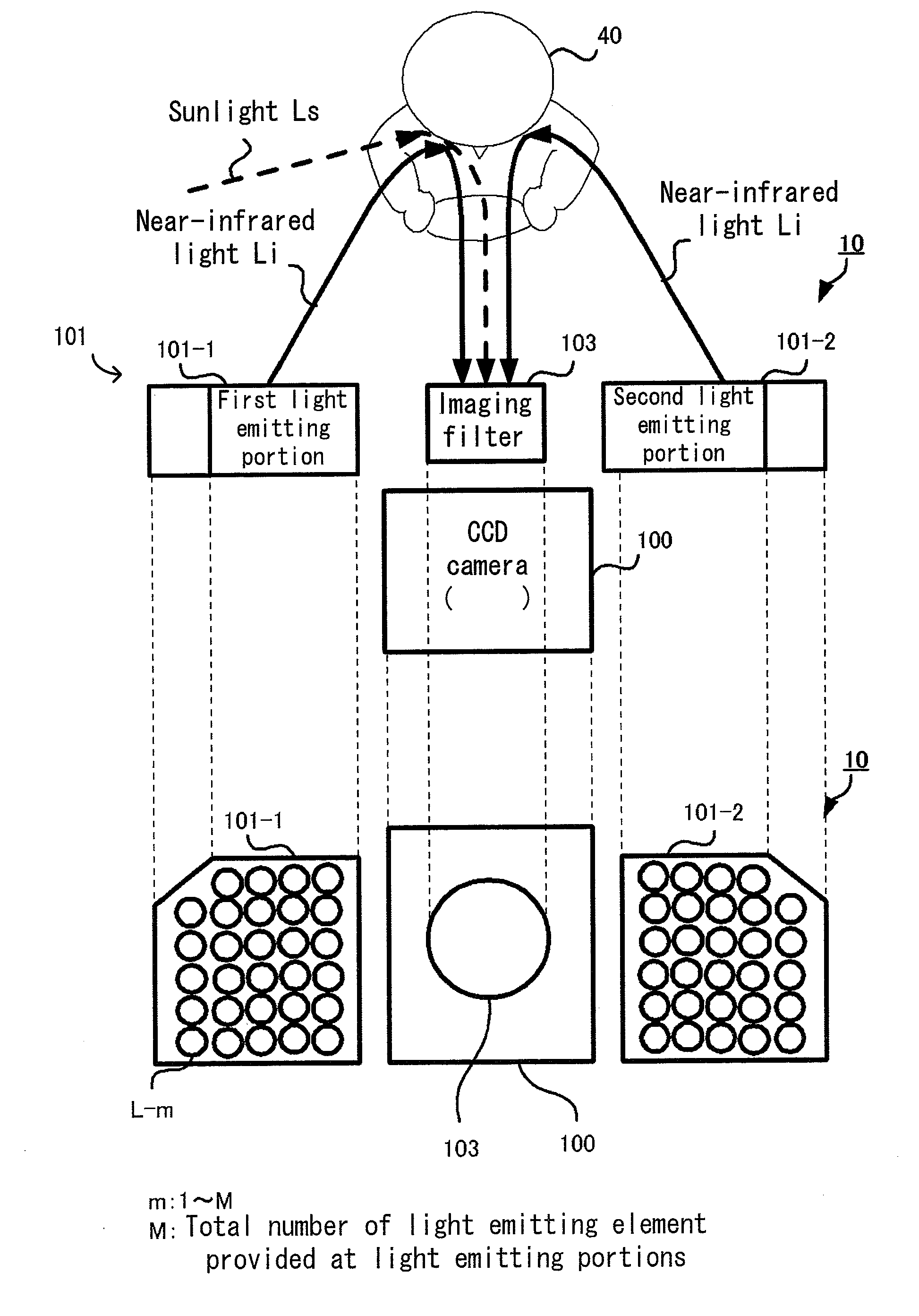
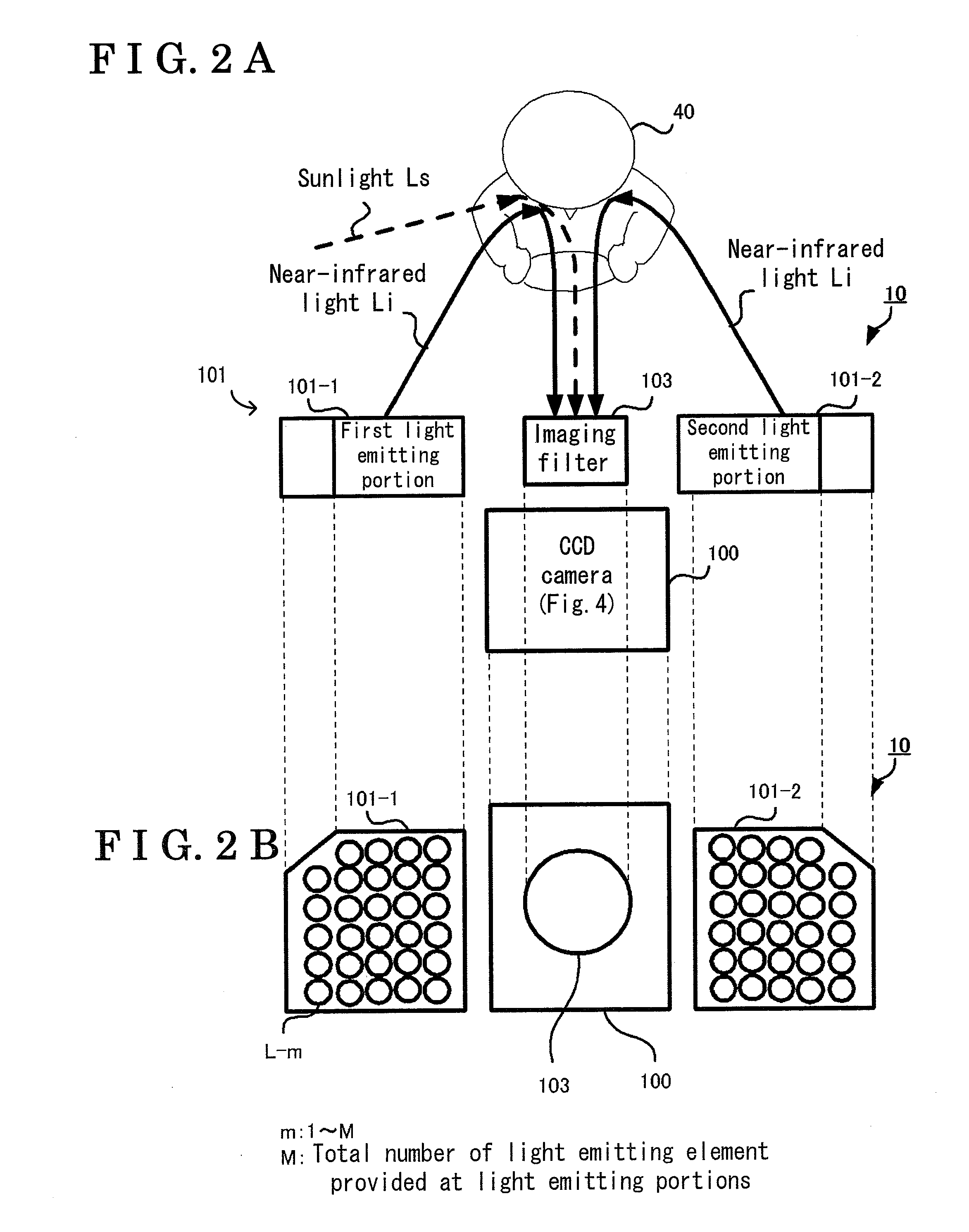
[0097]In the first and second embodiments, the direct sunlight control and the reflection on eyeglasses control are executed by means of each of the light emitting portions 101-n in which the number, the current value and the alignment of the near-infrared LED are determined on the basis of the sunlight intensity Is that is previously measured by the measuring device 20 at the design stage.
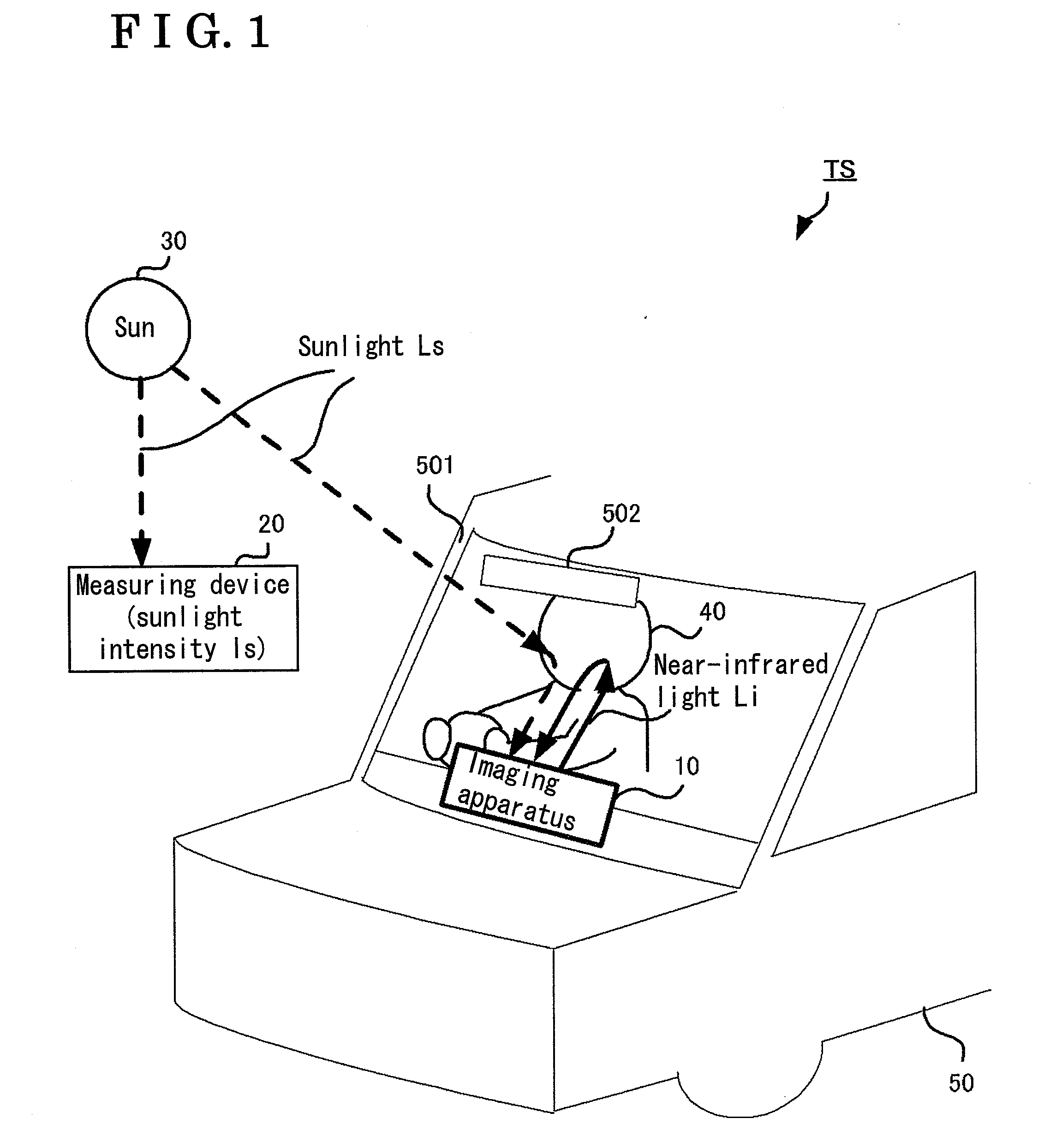
[0098]In the third embodiment, the measuring device 20 is mounted to an automobile 50, the imaging apparatus 10 obtains the sunlight intensity Is measured by the measuring device 20, and the imaging apparatus 10 controls the first light emitting portion 101-1 and the second light emitting portion 101-2 to emit the light on the basis of the sunlight intensity Is in a manner where the direct sunlight control and the reflection on eyeglasses control are executed (the formulas 1 and 2 are fulfilled).
[0099]A configuration of the imaging system TS of the third embodiment will be explained. A system conf...
PUM
 Abstract
Description
Claims
Application Information