
Camera module for vehicle vision system

a camera module and vehicle technology, applied in the field of vehicle vision systems, can solve the problems of undesirable instability of the image displayed to the driver of the vehicle, lack of substantially water tight seal,

Inactive Publication Date: 2009-10-01
MAGNA ELECTRONICS
View PDF83 Cites 308 Cited by
  • Summary
  • Abstract
  • Description
  • Claims
  • Application Information

AI Technical Summary

Benefits of technology

[0007]Preferably, the outer shell is molded over the circuit board assembly via a low pressure molding process. The outer shell thus may substantially seal the circuit board and circuitry therewithin to provide enhanced protection of the circuitry against the environment at which the camera module may be positioned.
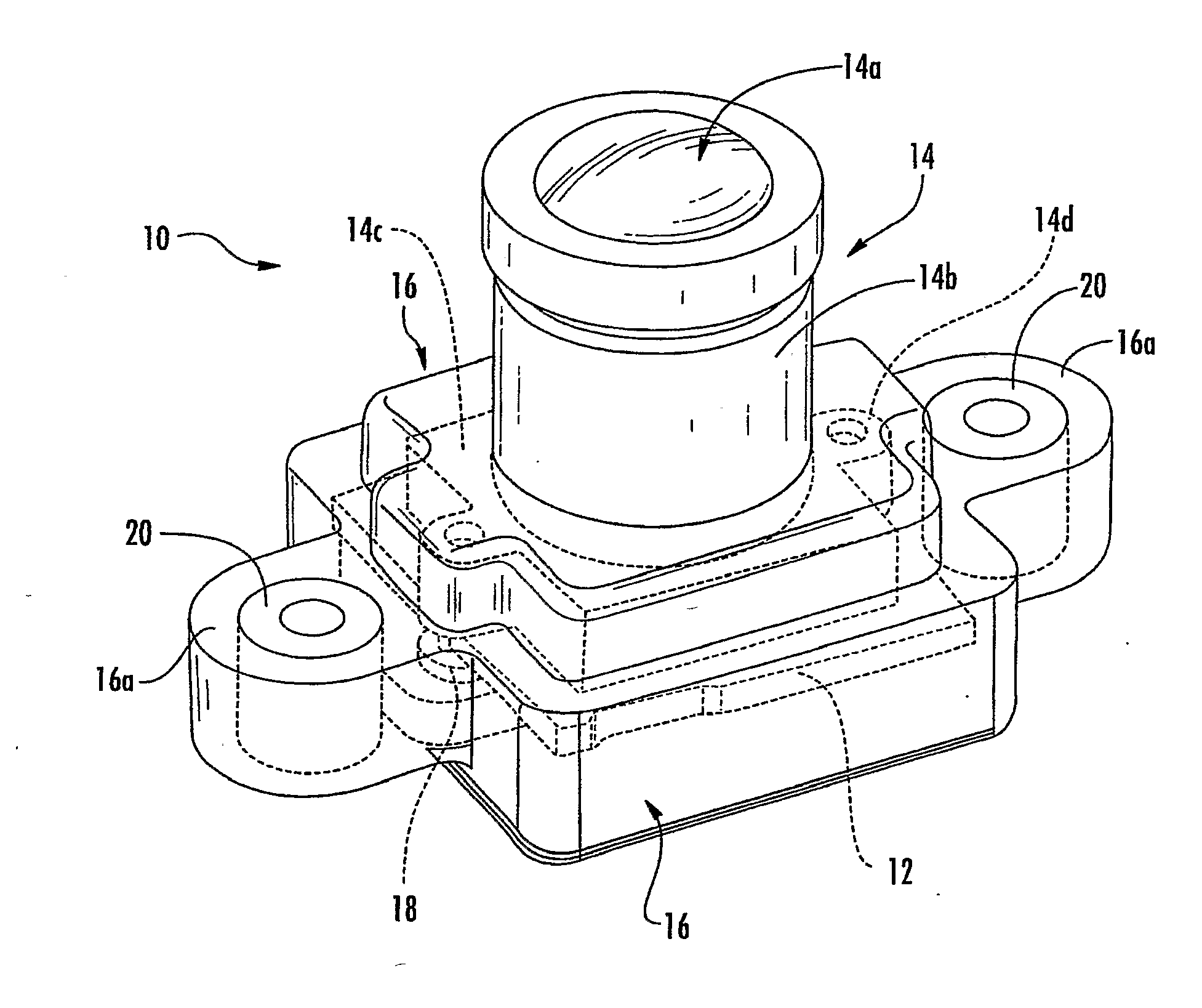
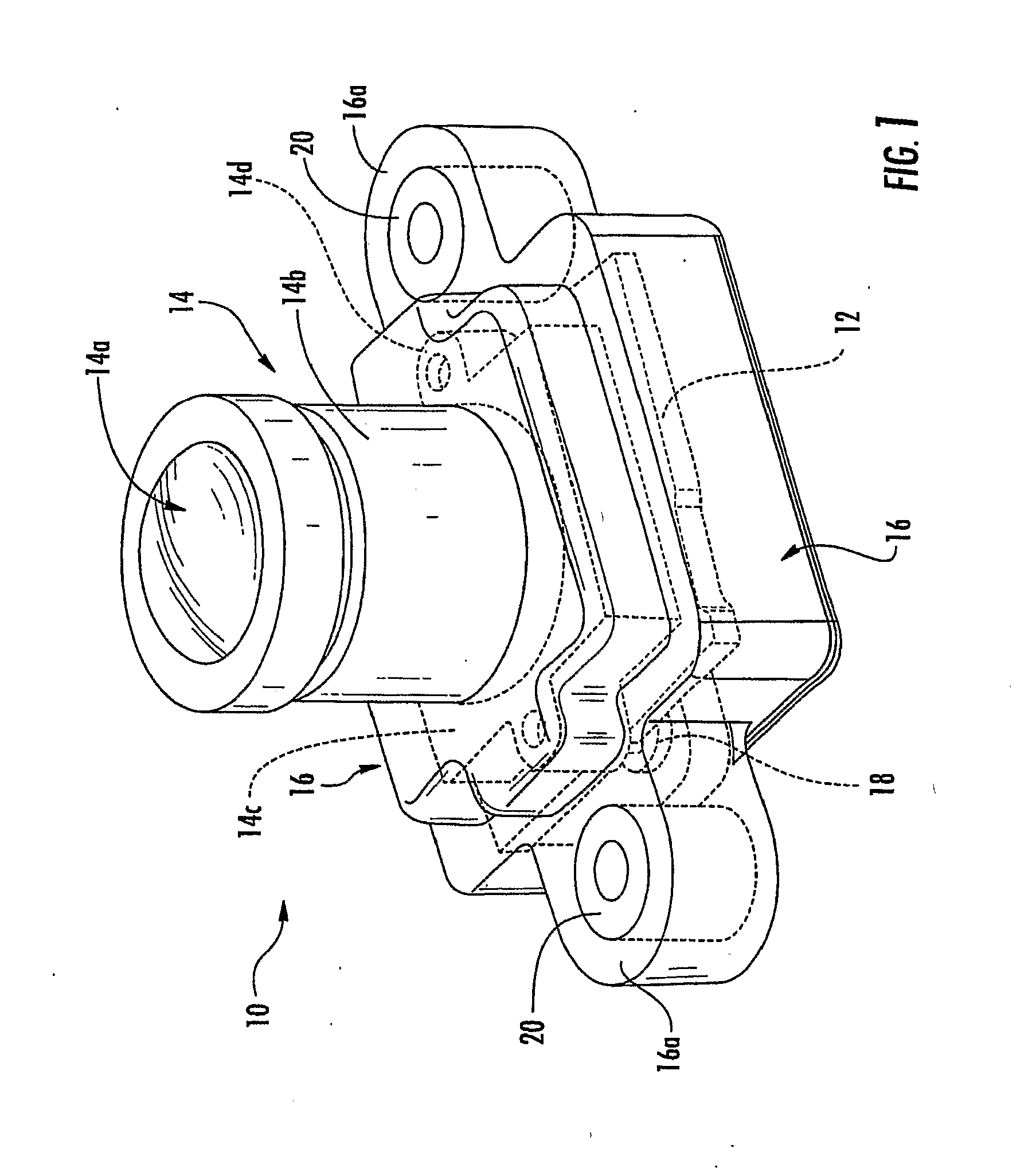
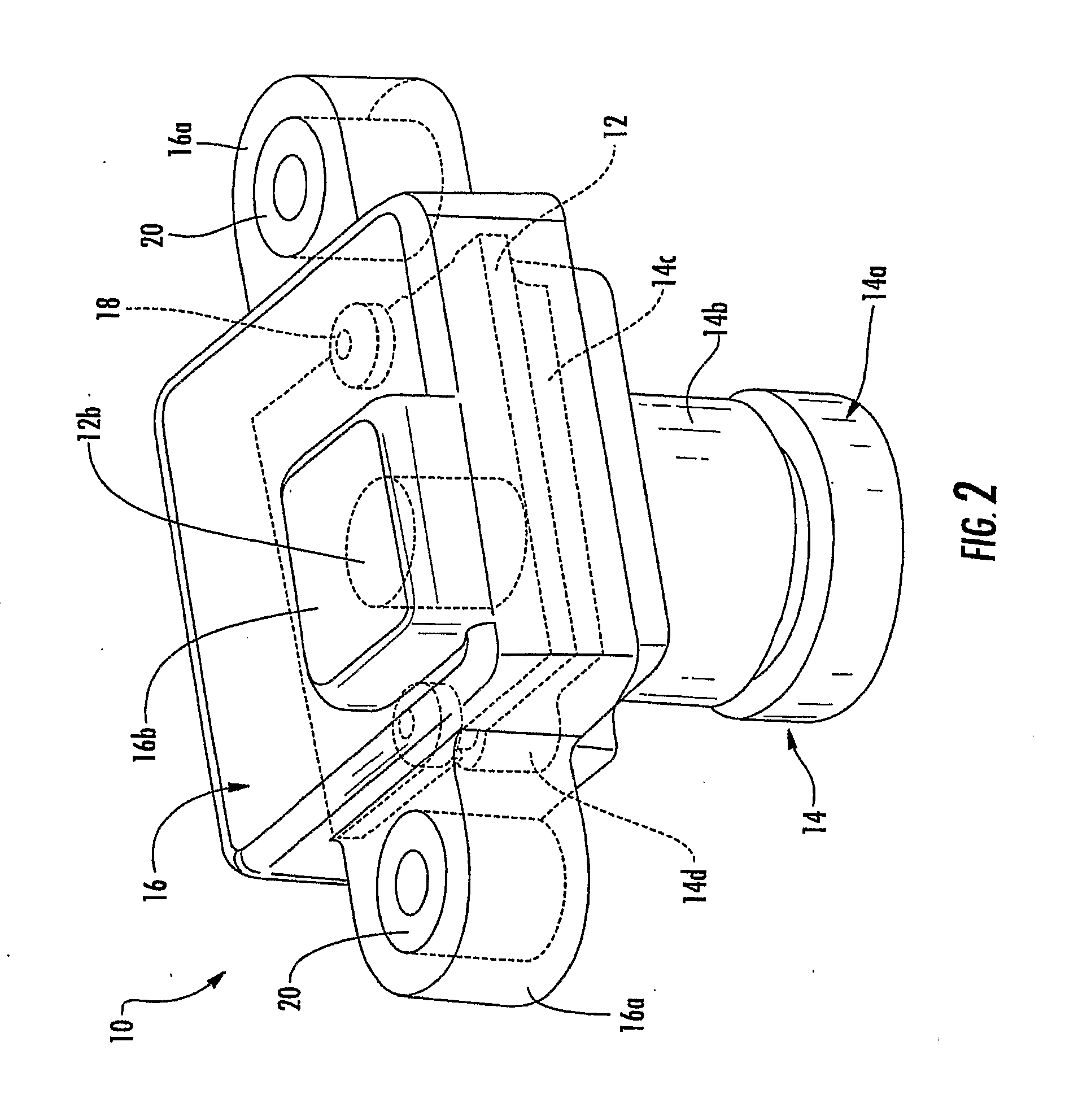
[0009]Therefore, the present invention provides a camera or imaging device or module that includes an imaging sensor and associated circuitry on a circuit element or circuit board or chip that is assembled to a lens assembly or to a lens mounting element or lens holder and that is substantially encased and sealed within a molded outer plastic or polymeric shell. By molding the outer shell around and over the circuit element and circuitry, the circuitry is substantially protected and sealed against water intrusion or other environmental elements and effects, and thus provides a substantially water impervious, robust camera module that may be highly suited for exterior vehicle applications. Also, by molding the outer shell over the circuit element, the outer shell (and the overall camera module) may be substantially smaller than known cameras that have the circuitry and sensor located within a hollow housing or casing.

Problems solved by technology

However, such housings typically do not provide a substantially water tight seal, and water droplets thus may enter the housing.
Furthermore, any excessive vibration of the camera sensor, due to its placement (such as at the exterior of the vehicle), may lead to an undesirable instability of the image displayed to the driver of the vehicle.
Also, such cameras or sensors are costly to manufacture and to implement on the vehicles.

Method used


Image

  • Camera module for vehicle vision system
  • Camera module for vehicle vision system
  • Camera module for vehicle vision system

Examples


Embodiment Construction

[0029]Referring now to the drawings and the illustrative embodiments depicted therein, a camera or imaging device or module 10 is adapted for use on or in or at a vehicle and is associated with at least one vision system of the vehicle. Camera module 10 includes a circuit board or chip or element 12 (on which an imaging sensor and associated circuitry is established), a lens assembly 14 and a molded encapsulant or overmold or outer shell 16. Lens assembly 14 is secured or attached to circuit board 12 such that the lens optic or optics 14a function to focus and direct and refract an image of the scene at the field of view of the lens optics onto the imaging sensor. Outer shell 16 is molded over and around the circuit board 12 and over a portion of the lens assembly 14 to substantially or entirely encase or encapsulate the circuit board 12 and circuitry within the molded outer shell 16, as discussed below.

[0030]The circuit board or element 12 of camera or imaging device module 10 incl...


PUM


Abstract

A camera module (10) for a vision system of a vehicle includes a circuit element (12), a lens mounting element (14b, 14c), a lens assembly (14) and an outer shell or cover portion (16). The circuit element includes an imaging sensor and associated circuitry (12a). The lens assembly includes at least one optical element (14a) and the lens mounting element (14b, 14c) is attached to the circuit element (12) so as to provide an optical path through the optical element to the imaging sensor at the circuit element. The outer shell (16) is molded over and around the circuit element during a molding process to substantially encapsulate the circuit element within the outer shell. The module and method of making the module thus may substantially seal the circuit element within the overmolded outer shell to protect the circuit element from exposure to the elements.

Description

CROSS REFERENCE TO RELATED APPLICATION[0001]The present application claims the benefit of U.S. provisional application Ser. No. 60 / 731,183, filed Oct. 28, 2005 (Attorney Docket DON01 P-1248), which is hereby incorporated herein by reference in its entirety.FIELD OF THE INVENTION[0002]The present invention relates generally to the field of vision systems for vehicles and, more particularly, to visions systems that include one or more imaging sensor positioned at the vehicle and having an interior or exterior field of view.BACKGROUND OF THE INVENTION[0003]The advent of low cost, reliable imaging devices, based on a variety of silicon technologies, and in particular CMOS technology, combined with an improved cost / performance ratio for displays capable of meeting automotive specifications, and an increasing application rate of video monitor displays for automotive navigation systems or as part of the driver interface to a wide variety of vehicle systems, has lead to an increasing use of...

Claims


Application Information

Patent Timeline
IPC IPC(8): H04N5/225
CPCH04N5/2253H04N5/2257H04N5/2254H04N23/57H04N23/55H04N23/54
Inventor GEBAUER, DUANE W.GIBSON, JOEL S.HUANG, SHIH-CHEIRELAND, HUGH W.
Owner MAGNA ELECTRONICS
Learn More