Stereoscopic-image display apparatus

a stereoscopic and display apparatus technology, applied in the field of stereoscopic image display apparatus, can solve the problems of difficult to see, inability to achieve satisfactory performance for stereoscopic display of multiple parallax, and inability to improve the comprehensive performance of stereoscopic display

Inactive Publication Date: 2009-10-01
KK TOSHIBA
View PDF7 Cites 46 Cited by
  • Summary
  • Abstract
  • Description
  • Claims
  • Application Information

AI Technical Summary

Benefits of technology

[0011]According to one aspect of the present invention, a stereoscopic-image display apparatus includes an elemental-image display unit that includes pixel plane on which pixels are arranged in matrix; a polarization switching cell that is arranged opposite to the elemental-image display unit, and that switches polarization direction thereof corresponding to applied voltage; a lens array lamination layer that includes refractive-index anisotropic mediums and substrates with two lens arrays whose principal planes are different from each other, the refractive-index anisotropic mediums making lens effect of either one of the lens arrays effective corresponding to the polarization direction switched by the polarization switching cell; a synchronization drive unit that controls voltage to be applied to the polarization switching cell synchronizing with a display timing of images displayed on the elemental-image display unit, and that switches the lens array to be effective at each display timing; and a display control unit that controls the elemental-image display unit to alternately display the images on near or far sides by time division multiplexing, synchronizing with the display timing, wherein focal planes of the two lens arrays are positioned at different positions from each other near the pixel plane.

Problems solved by technology

On the other hand, the two-view type and the multiview type have such a problem that a range of positions of the viewpoint enabling stereoscopic view, that is, a viewing zone is narrow, making it difficult to be seen.
However, as for the depth multiplexing type, such a simple configuration that is applicable to a flat panel type has not been known, and various techniques to improve the comprehensive performance of stereoscopic display have been proposed.
However, with the technique described in “SID04 Digest 1438 (2004)”, satisfactory performance cannot be obtained for stereoscopic display of multiple parallax, and the comprehensive performance of stereoscopic display cannot be improved.
Further, in the technique described in JP-A 2005-340957, the distance between lens pixels is mechanically changed, and therefore, the configuration is complicated.
As a result, a switching speed high enough for the time division multiplexing cannot be achieved.
Therefore, similarly to the above case, the comprehensive performance of stereoscopic display cannot be improved.

Method used


Image

  • Stereoscopic-image display apparatus
  • Stereoscopic-image display apparatus
  • Stereoscopic-image display apparatus

Examples


first embodiment

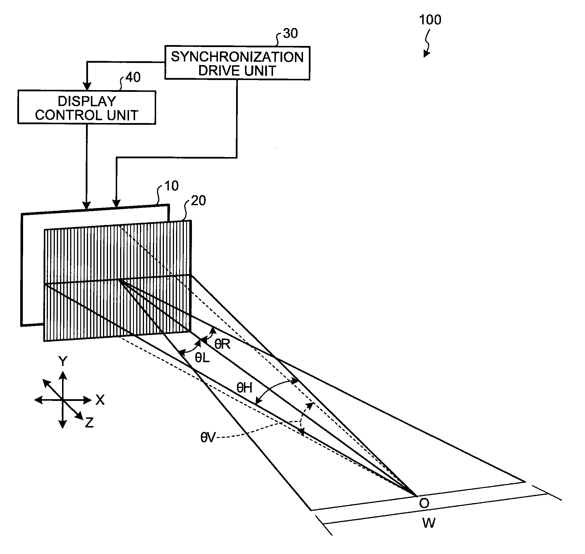
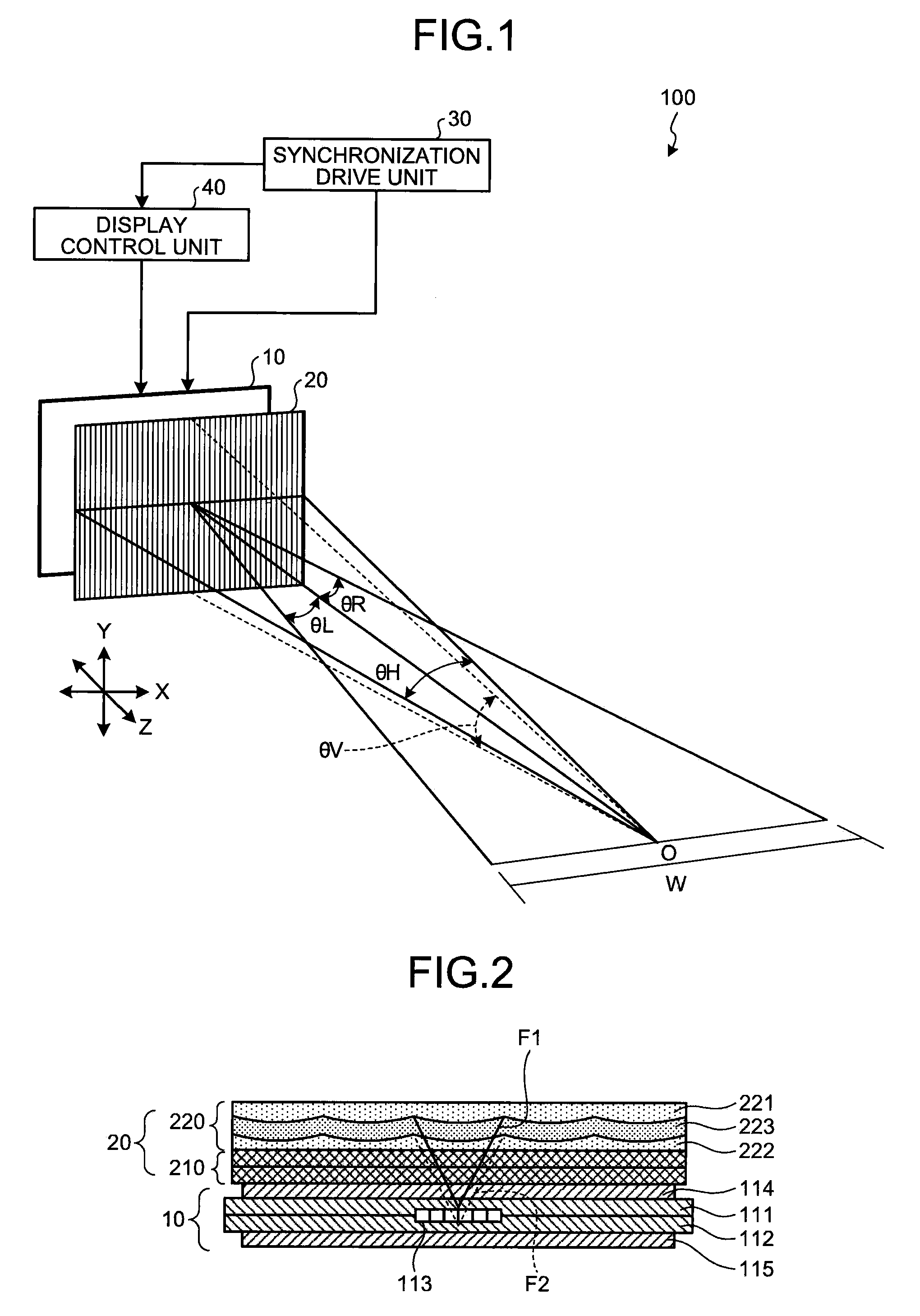
[0041]A configuration of the elemental-image display unit 10 and the lens array unit 20 (hereinafter, “display unit” collectively) according to the present invention is explained below in detail.

[0042]FIG. 2 is a schematic diagram illustrating a cross-section in a horizontal direction (X axis direction in FIG. 1) of the display unit according to the first embodiment. As shown in FIG. 2, the elemental-image display unit 10 includes glass substrates 111 and 112, a pixel plane 113 of a liquid crystal panel that is arranged between the glass substrates 111 and 112, and polarizers 114 and 115 that are arranged on outer surfaces of the glass substrates 111 and 112. Each pixel constituting the pixel plane 113 is constituted by sub-pixels that have three color components (red, green, blue) in at least one of a horizontal direction and a vertical direction as described later.

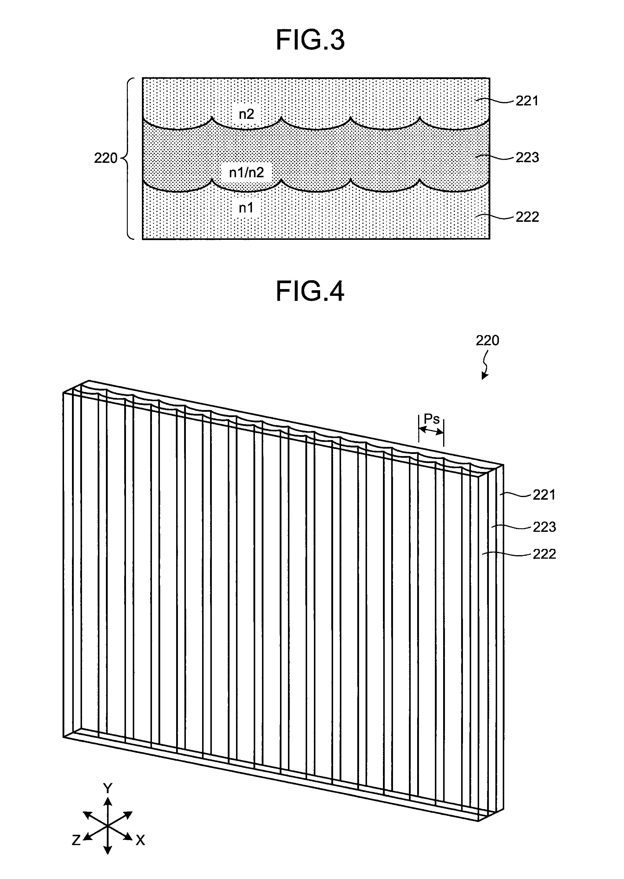
[0043]The lens array unit 20 includes a polarization switching cell 210 and a lens array lamination layer 220. As the ...

second embodiment

[0075]FIG. 12 is a schematic diagram illustrating a cross-section of a display unit according to the As shown in FIG. 12, a lens array unit 50 includes the polarization switching cell 210 and a lens array lamination layer 510. The lens array lamination layer 510 is constituted by substrates 511 and 512 and mediums 513, 514, and 515 in three layers that contact on two interfaces that form curved surfaces of a lens. The form of the curved surfaces of the lens can be a fly-eye lens form or a cylindrical lens form (form of lenticular sheet).

[0076]FIG. 13 is a partial enlarged view of the lens array lamination layer 510. As shown in FIG. 13, the mediums 513 and 515 are arranged such that convex curved surfaces of the lens are opposite to each other, and the medium 514 is sandwiched between the mediums 513 and 515. The mediums 513 and 515 are a refractive-index anisotropic medium in which the refractive index changes corresponding to the polarization direction of incident light. The medi...

third embodiment

[0093]FIG. 17 is a schematic diagram illustrating a cross-section in a horizontal direction of a display unit according to the As shown in FIG. 17, a lens array unit 60 includes a polarization switching cell 210 and a lens array lamination layer 610. The lens array lamination layer 610 is constituted by a substrate 611 in a flat plane form, two substrates 612 and 613 having curved surfaces in a lens array, and mediums 614 and 615 in two layers that are filled between the substrates. The form of the curved surfaces of the substrates 612 and 613 can be a fly-eye lens form or a cylindrical lens form (form of lenticular sheet).

[0094]FIG. 18 is a partial enlarged view of the lens array lamination layer 610. The medium 614 is a refractive-index anisotropic medium, and has refractive indexes n1 and n2 to two polarization directions that are perpendicular to each other as the optical characteristic. Moreover, the medium 614 forms a flat lens layer as a whole together with the substrate 612...


PUM

PropertyMeasurementUnit
aspect ratioaaaaaaaaaa
applied voltageaaaaaaaaaa
voltageaaaaaaaaaa

Abstract

Mediums that are arranged opposite to an elemental-image display unit, that form two lens arrays having different principal planes together with substrates, and that switches a polarization direction of incident light corresponding to applied voltage, thereby making lens effect of either one of the lens arrays effective are included. By controlling the polarization direction synchronizing with a display timing of images to be displayed on the elemental-image display unit, the lens array to be effective is switched at each display timing, and images having different near or far direction are alternately displayed on the elemental-image display unit.

Description

CROSS-REFERENCE TO RELATED APPLICATIONS[0001]This application is based upon and claims the benefit of priority from the prior Japanese Patent Application No. 2008-86254, filed on Mar. 28, 2008; the entire contents of which are incorporated herein by reference.BACKGROUND OF THE INVENTION[0002]1. Field of the Invention[0003]The present invention relates to a stereoscopic-image display apparatus.[0004]2. Description of the Related Art[0005]As a stereoscopic-image display device, which is what is called a three-dimensional display, that can display a moving image, various types of devices are known. Particularly, a flat panel type not requiring special eyeglasses or the like is in increasing demand in recent years. Among stereoscopic-image display devices of this type, while it is difficult to realize full-color moving image with a type in which principles of holography are applied, with a type in which a beam control device that controls light beams from a display panel to emit toward ...

Claims


Application Information

Patent Timeline
Patent Type & Authority Applications(United States)
IPC IPC(8): G02B27/26G02F1/01G02F1/29G02B27/22G02B30/25
CPCH04N13/0406H04N13/0404H04N13/305H04N13/307
Inventor SAISHU, TATSUOKASHIWAGI, MASAKOTAKAGI, AYAKOTAIRA, KAZUKI
Owner KK TOSHIBA
Why Eureka
Try Eureka