Visible light communication apparatus

Inactive Publication Date: 2009-10-01
PLANNERS LAND
View PDF5 Cites 28 Cited by
  • Summary
  • Abstract
  • Description
  • Claims
  • Application Information

AI Technical Summary

Benefits of technology

[0023]According to the present invention, the necessity for installing a complicated demodulator circuit or detection circuit on the side of the receiver is eliminated, a circuit on the side of the receiver is greatly simplified and streamlined in constitution, thus making it possible to realize a one-chip receiver. It is also possible to reduce greatly the production cost of a visible light communication apparatus.
[0024]As described above, according to the visible light communication apparatus of the present invention, white light containing a blue light component is radiated as visible illumination light from a lamp fitting, and a blue light photodiode for receiving blue light at the highest sensitivity is used to receive the white light, thus making it possible to receive the blue light component contained in the white light at high sensitivity and also receive it so as to respond at high speed. Therefore,

Problems solved by technology

However, in wireless communications in which radio waves are used as a medium, it is impossible to increase the transmission power, with the influence of electromagnetic waves on the human body taken into account, where the transmitting and receiving are performed near people.
Further, since the frequency range of radio waves used in wireless communications has already been allocated in many areas and actually used, it is impossible to use freely frequencies over a wide range.
Still further, under special circumstances such as medical institutions, there are some restrictions, for example, the limited use of radio waves.
Fur

Method used


Image

  • Visible light communication apparatus
  • Visible light communication apparatus
  • Visible light communication apparatus

Examples


Embodiment Construction

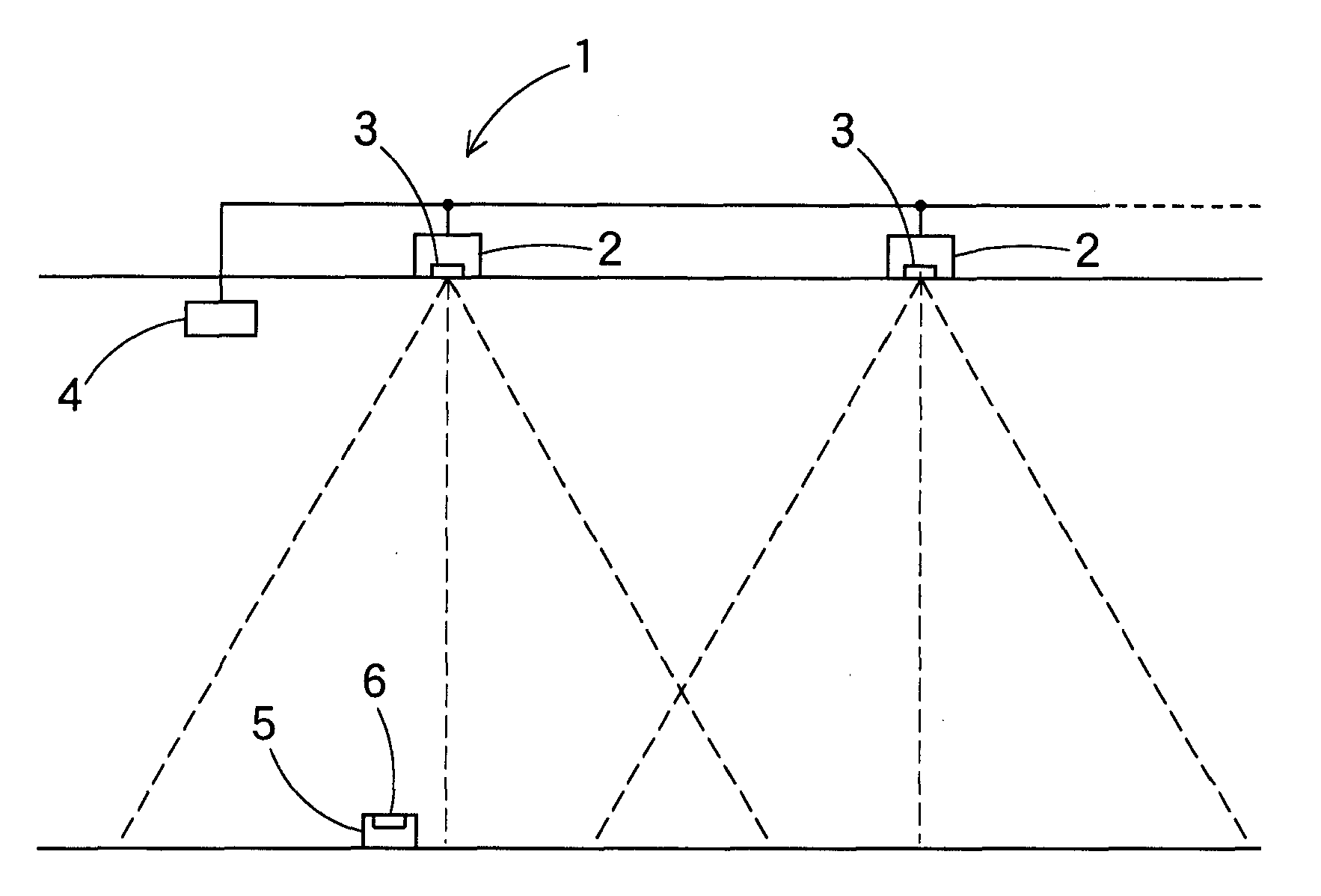
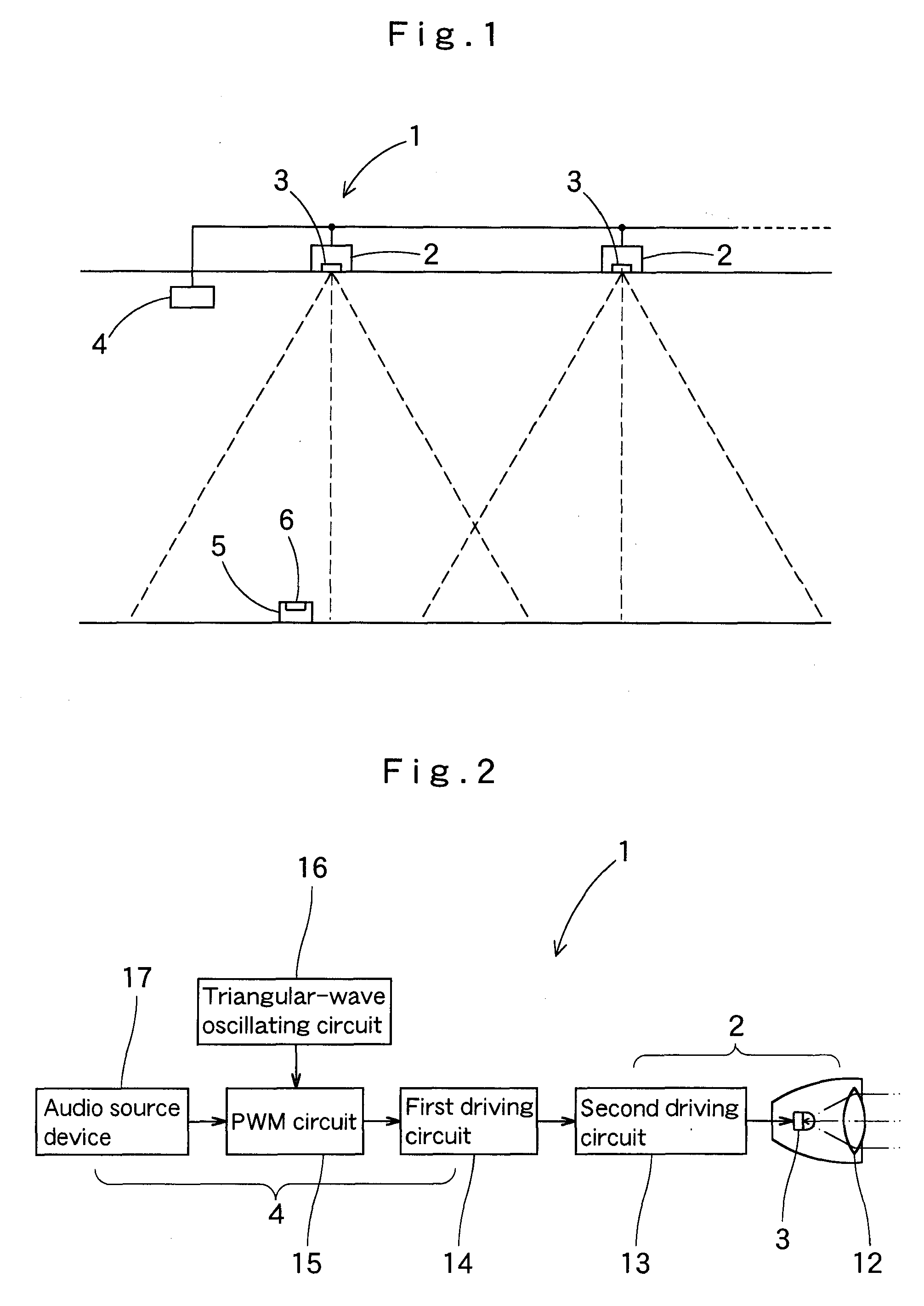
[0031]Hereinafter, a description will be given to an embodiment of the present invention with reference to the drawings. In addition, the present invention shall not be limited to the embodiment. Any modification within requirements of the claims or equivalents of the requirements shall be included within the scope of the claims. FIG. 1 is a schematic constitutional view showing a visible light communication apparatus, FIG. 2 is a block diagram of a transmitter 1 thereof, and FIG. 6 is a block diagram of a receiver 5 thereof. The visible light communication apparatus is used, for example, in an underground shopping center or the like, and the transmitter 1 illuminates stores and pathways at an underground shopping center by means of a lamp fitting 2, while superimposing various types of information signals such as audio guidance on visible light (white light) of the lamp fitting 2 to transmit them. The receiver 5 is installed in any place such as pathways and stores in an undergroun...


PUM


Abstract

A visible light communication apparatus is constituted with a transmitter for illuminating and projecting visible light on which an information signal is superimposed from a lamp fitting and a receiver for receiving the visible light to take out the information signal superimposed on the visible light. The transmitter modulates a transmission information signal, driving a light projecting element of the lamp fitting so as to superimpose the transmission information signal on the visible light of the lamp fitting, thereby radiating white light containing a blue light component as visible illumination light. The receiver receives the white visible light containing the blue light component radiated from the transmitter and generates a receiving information signal from the light receiving signal on a receiving circuit. A blue light photodiode which receives blue light at the highest sensitivity to output a light receiving signal is used as a light receiving element of the light receiving unit. The lamp fitting for radiating the white light containing the blue light component on the side of the transmitter as visible illumination light and the blue light photodiode for receiving blue light on the side of the receiver at the highest sensitivity can be used to perform visible light communications at high speed, while illuminating by the white light.

Description

BACKGROUND OF THE INVENTION[0001]1. Field of the Invention[0002]The present invention relates to a visible light communication apparatus for performing communications by using visible light radiated in a space and in particular to the visible light communication apparatus capable of performing communications at high speed by means of a relatively simplified circuit.[0003]2. Description of Related Art[0004]Wireless communications by using radio waves as a communication medium have found many uses in various fields such as cellular phone networks, wireless LANs and short-distance wireless communications.[0005]However, in wireless communications in which radio waves are used as a medium, it is impossible to increase the transmission power, with the influence of electromagnetic waves on the human body taken into account, where the transmitting and receiving are performed near people. Further, since the frequency range of radio waves used in wireless communications has already been alloc...

Claims


Application Information

Patent Timeline
IPC IPC(8): H04B10/00H04B10/11H04B10/116
CPCH04B10/116H04B10/1141
Inventor MURAYAMA, FUMITAKAKUROKAWA, HIROYUKIFURUTA, NAOYUKI
Owner PLANNERS LAND
Why Eureka
Try Eureka