Ball and socket joint

a socket joint and ball socket technology, applied in the direction of shafts, bearings, pivots, etc., can solve the problems of inability to meet the specifications mandated by law regarding the steering return, assume considerable high values, adverse effects, etc., and achieve low friction, improved absorption of both radial and axial loads, and simplified manufacturing

Inactive Publication Date: 2009-10-01
ZF FRIEDRICHSHAFEN AG
View PDF16 Cites 7 Cited by
  • Summary
  • Abstract
  • Description
  • Claims
  • Application Information

AI Technical Summary

Benefits of technology

[0017]Another essential advantage of the present invention is seen by the inventors in the fact that the axis of rotation of the rollers of the roller bearings forms an angle with the longitudinal axis of the ball pivot. This means, from a practical point of view, that the rollers are in an oblique position. It becomes possible due to this arrangement of the rollers to improve the absorption of both radial and axial loads without the favorable properties of the ball and socket joint, which can be seen especially in the extremely low friction during rotary motion of the ball pivot, being reduced.
[0018]According to another embodiment of this idea, the angle may be between 0° and 90°. However, arrangements of the rollers in relation to the longitudinal axis of the ball pivot at an angle of 45° are preferred. It was found that the arrangement at 45°, in particular, makes possible a very advantageous transmission of forces and can thus best meet the requirements imposed on the ball and socket joint.
[0019]It is, moreover, proposed in connection with a simplified manufacture and the associated cost reduction in the manufacture of ball and socket joints according to the present invention to create a kind of modular system. Accordingly, one solution according to the present invention proposes that the ball pivot have an at least two-part joint ball and that the roller bearing be accommodated within the joint ball assembled. The at least two-part design of the joint ball leads to leeway in terms of design, which makes possible a high level of variability of the individual components depending on the requirements imposed on the joint. The great flexibility is associated with the possibility of using standardized components.
[0020]The inventors perfected this inventive idea described above to the extent that the rollers can be arranged loosely in running track surfaces suitable for this between the corresponding joint ball parts. This means that no roller bearings finished in advance need to be used to implement the solution according to the present invention, but it is thus possible to embody a very simple mounting of the ball and socket joint according to the present invention by means of a running track within the joint ball parts corresponding to one another and rollers inserted therein and, moreover, to provide the arrangement of the rollers between the joint ball parts in a desired manner. It is thus also possible without difficulties to implement the oblique positions of the rollers mentioned in the introduction relative to the longitudinal axis of the ball pivot. The running track surfaces provided within the joint ball parts must only be suitable for accommodating and correspondingly guiding the rollers.
[0021]One embodiment of the present invention can be seen in the fact that the roller forms a rotating track within the ball and socket joint.
[0022]To improve comfort and to reduce the transmission of structure-borne noise in a ball and socket joint according to the present invention, the inventors propose, furthermore, to mount the joint ball as a whole pivotably in a bearing shell accommodated in the housing. Such a bearing shell has the advantage that it reduces, i.e., absorbs vibrations introduced via the ball and socket joint, on the one hand, and eliminates the need for maintenance for the ball and socket joint, on the other hand. Due to the use of an elastic bearing shell, it is consequently unnecessary to lubricate the ball and socket joint later at specified maintenance intervals. Suitable materials for the bearing shell are known from the state of the art. For example, materials such as POM, PEEK or similar materials with good tribological properties, which reduce the overturning moments to a minimum in this case, can be used especially advantageously. Some of these maintenance-free materials possess self-lubricating properties, and they also lead, moreover, to the above-mentioned absorbing properties.

Problems solved by technology

Ball and socket joints are subject in motor vehicles to radial and axial forces, which may at times assume considerably high values.
This has an adverse effect especially in the area of the steering, because increased forces are to be applied here in order to guarantee steerability of the motor vehicle.
Moreover, high torques and moments of friction within the ball and socket joint lead to wear as well as to the risk that specifications mandated by law concerning the steering return cannot be met.
However, the ball and socket joints known from said documents also have drawbacks.
However, this is associated with a reduction of comfort, which is not acceptable.
However, the essential drawback of the ball and socket joint designs known from U.S. Pat. No. 2,954,993 and U.S. Pat. No. 2,645,510 can be seen in the fact that the roller bearings used are designed exclusively for loading in the axial direction relative to the non-deflected ball pivot.
The roller bearings used here are not suitable for absorbing and passing on radial forces.
Moreover, the problem arises in such roller bearings that the clearance also increases with the roller bearing when wear develops on the joint and an associated loosening of the inner components of the joint occurs.
However, it can happen as a result that the rollers will be displaced and jammed and their trouble-free operation is thus not guaranteed any longer.
However, cylindrical roller bearings can transmit only extremely weak axial forces at best.
Such a ball and socket joint can have very limited use only in case of the complex loads to which a ball and socket joint is subject in a motor vehicle, which also involve superimposed force and torque effects in the axial as well as radial directions.

Method used


Image

  • Ball and socket joint
  • Ball and socket joint

Examples


Embodiment Construction

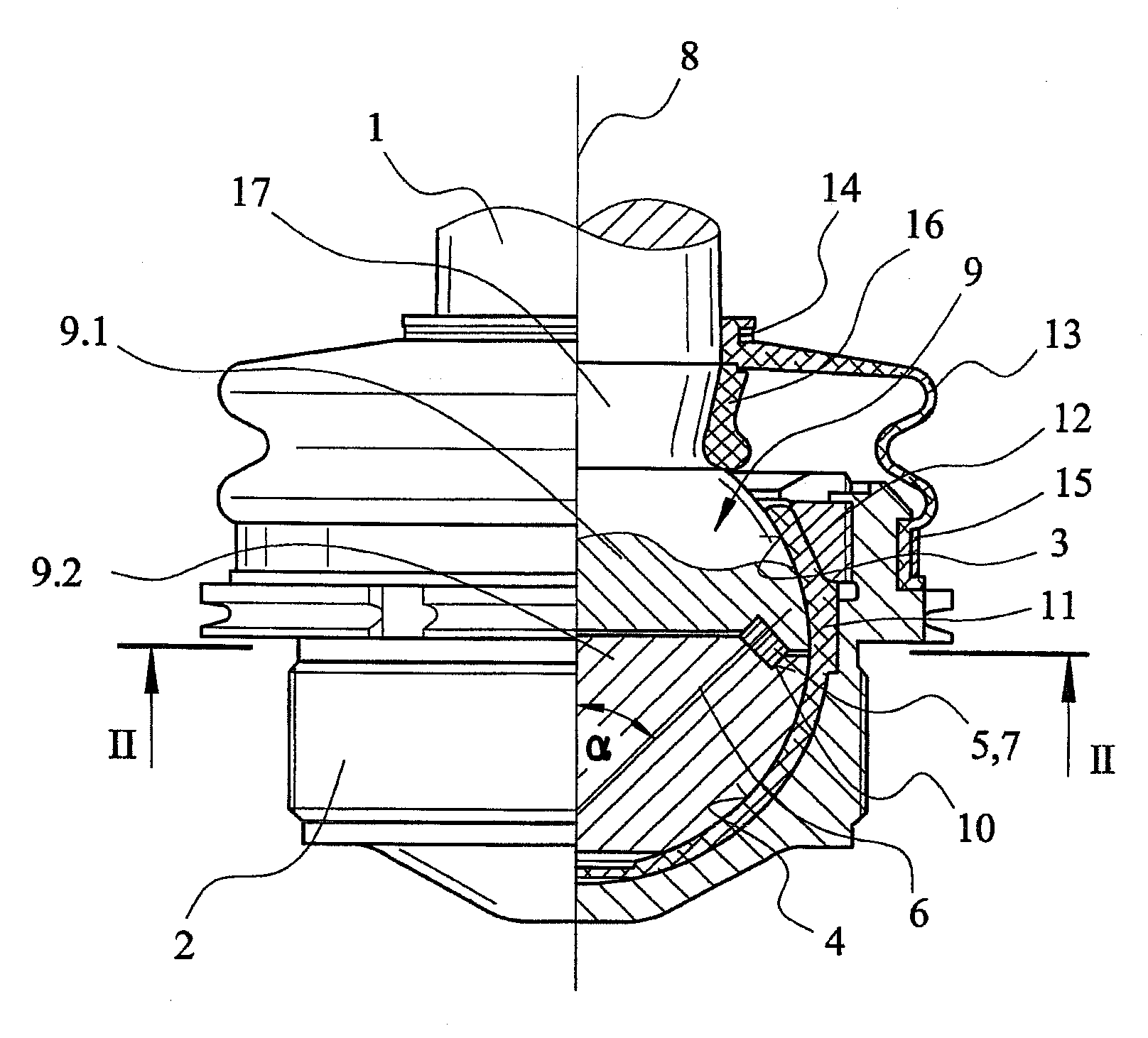
[0028]Referring to the drawings in particular, FIG. 1 shows an example of an embodiment variant of a ball and socket joint according to the present invention as a partial section. This ball and socket joint has a ball pivot 1, which is mounted pivotably and rotatably in a housing 2. In the example being shown, the housing-side end area of the ball pivot 1 has a first spheroidal bearing surface 3, which forms a joint ball designated as a whole by 9 together with a second spheroidal bearing surface 4 connected to the ball pivot 1.

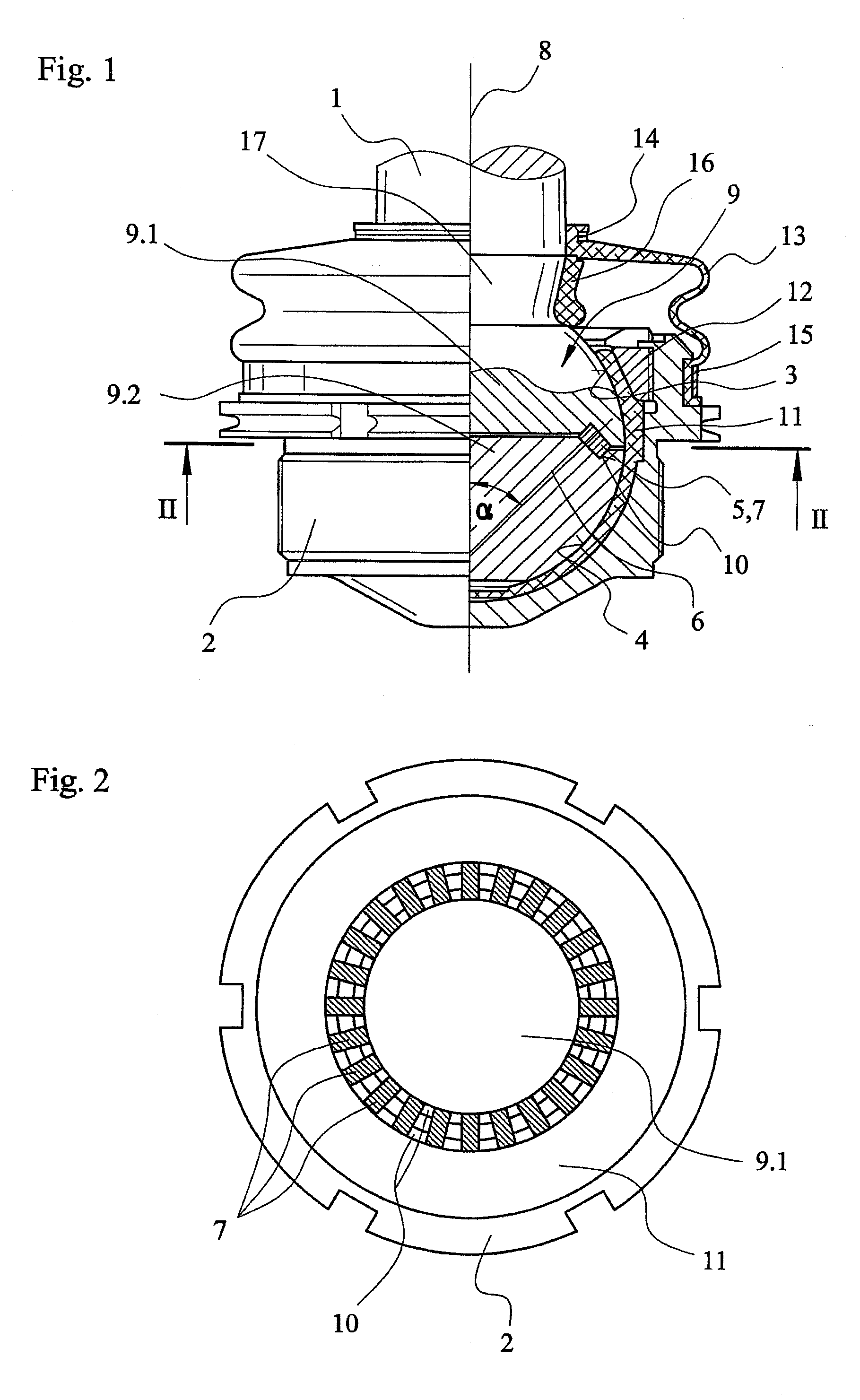
[0029]A roller bearing 5 is inserted between the joint ball parts 9.1 and 9.2. This roller bearing 5 comprises running tracks 10, which are present in the joint ball parts 9.1 and 9.2 and into which numerous rollers 7 are inserted loosely. The peculiarity according to the present invention is that the rollers 7 assume an oblique position in relation to the central longitudinal axis 8 of the ball pivot 1. An oblique position is defined here as a sloped install...


PUM


Abstract

A ball and socket joint is provided, especially for the wheel suspension of a motor vehicle, with a ball pivot (1), which is equipped with a first spheroidal bearing surface (3) mounted pivotably and rotatably in a housing (2). A roller bearing (5) is present between the first spheroidal bearing surface (3) and another spheroidal bearing surface (4), which is mounted in the housing (2) and is connected to the ball pivot (1). The roller bearing (5) is a roller bearing transmitting radial and axial forces.

Description

CROSS REFERENCE TO RELATED APPLICATIONS[0001]This application is a United States National Phase application of International Application PCT / DE 2007 / 000718 and claims the benefit of priority under 35 U.S.C. § 119 of German Patent Application DE 10 2006 020 397.6 filed Apr. 28, 2006, the entire contents of which are incorporated herein by reference.FIELD OF THE INVENTION[0002]The present invention pertains to a ball and socket joint, especially for the wheel suspension of a motor vehicle, which a ball pivot, which is equipped with a first spheroidal bearing surface mounted pivotably and rotatably in a housing, wherein a roller bearing is present between the first spheroidal bearing surface and another spheroidal bearing surface, which is mounted in the housing and is connected to the ball pivot.BACKGROUND OF THE INVENTION[0003]Ball and socket joints, as they are used especially for wheel suspensions in motor vehicles, are at times subject to extreme loads, which may consist of mechan...

Claims


Application Information

Patent Timeline
Patent Type & Authority Applications(United States)
IPC IPC(8): F16C11/06
CPCF16C11/0604Y10T403/32721Y10T403/32737Y10T403/32681Y10T403/32631Y10T403/32672
Inventor BRUNNEKE, HANS-GERD
Owner ZF FRIEDRICHSHAFEN AG
Why Eureka
Try Eureka