Indexable Cutting Tool Insert For Cutting Tools

Inactive Publication Date: 2009-10-01
REMARK TECH
View PDF39 Cites 16 Cited by
  • Summary
  • Abstract
  • Description
  • Claims
  • Application Information

AI Technical Summary

Benefits of technology

[0022]To hold the insert in the pocket, the tool holder body has a side wall of the seating pocket that is inclined over the seating surface and, thus, arranged to hold the indexable cutting insert in the pocket in a direction generally normal to the seating surface. By one approach, the side wall forms a dovetail configuration to aid in holding the insert to the seating surface. A fastener may also be used. To this end, the cutting tool insert side wall may also be inclined in an opposite and complementary fashion to the dovetail inclination of the seating pocket side wall to mate with the tool body. Due to this dovetail configuration of the side walls, loads generating by the machining are applied not only through the fastener, but also through the dovetailed engagement with the insert. By contrast, prior cutting tool designs utilized generally vertical walls or outwardly inclined walls and relied solely on the fasteners as the only structure which would resist movement of the insert away from the tool body. In prior tool bodies, the walls did not resist movement of the tool in a direction normal to the tool's seating surface and the fastener itself was generally the only structure that absorbed loads from the cutting application. The inserts and cutting tools herein, on the other ha

Problems solved by technology

Because of this construction of prior inserts, the unused cutting surfaces, when mounted in a fixed tool holder of a lathe, are still positioned at the outer surface of the cutting tool holder where

Method used


Image

  • Indexable Cutting Tool Insert For Cutting Tools
  • Indexable Cutting Tool Insert For Cutting Tools
  • Indexable Cutting Tool Insert For Cutting Tools

Examples


first embodiment

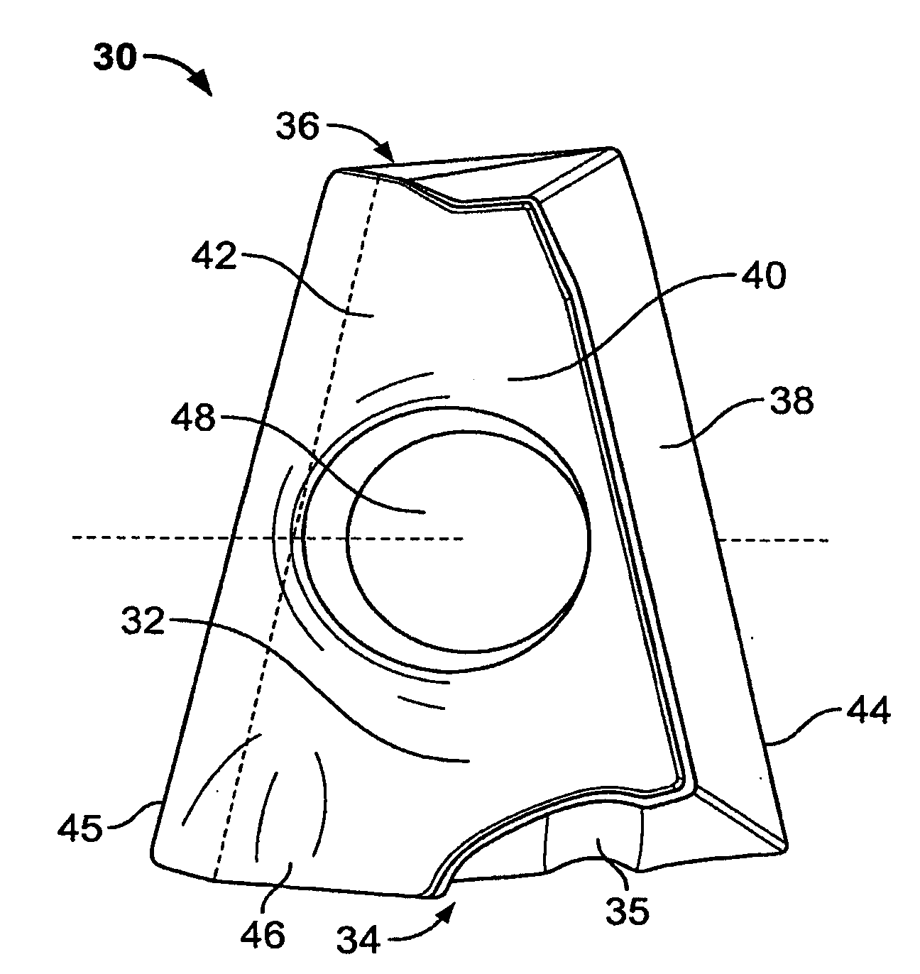
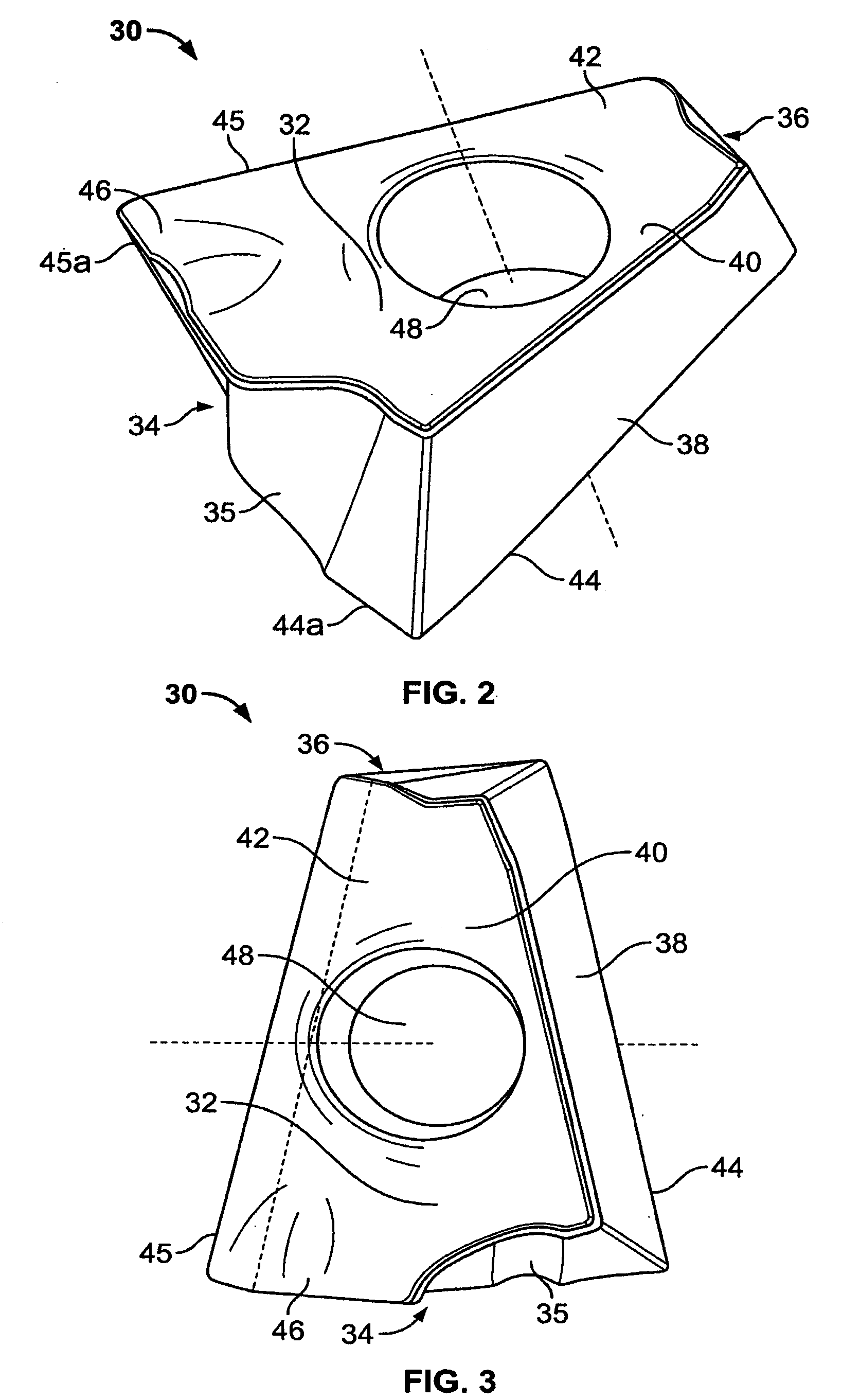
[0054]FIGS. 2-5 show a cutting tool insert 30. The insert 30 is a positive geometry insert composed of a block of hard metal that acts as a suitable cutting material, such as tungsten carbide. As can be seen in FIGS. 2, 3, and 11, the insert 30 has two opposed major faces 32 and 132, which are substantially parallel to one another and substantially identical in shape and area. Each opposed major face 32 or 132 has a truncated pie shape, in which each face 32 or 132 has a broad end 34 that tapers to a narrow end 36.

[0055]As can be seen in FIGS. 2, 3, and 11, the insert 30 has first and second edge surfaces, or side seating surfaces, 38 and 39 that form the sides of the insert 30 and that diverge from the broad end 34 of the insert 30 to the narrow end 36. The first and second side seating surfaces 38 and 39 act as clearance faces for rotary cutting action during the machining process. The first and second side seating surfaces 38 and 39 are oriented such that a cross-section of the i...

second embodiment

[0063]Further, the retainer hole 48 of the second embodiment is preferably elongated, as shown in FIG. 7. The elongated shape allows a retainer to be installed through the retainer hole 48 in one of two angled, non-perpendicular orientations. The two orientations of the retainer with respect to the insert 130 allow the use of four cutting edges along the insert 130, instead of two cutting edges.

[0064]More specifically, as shown in FIG. 9, the second embodiment has a first cutting edge 44, a second cutting edge 45, a third cutting edge 144, and a fourth cutting edge 145. These cutting edges are formed by the intersection of the side seating surfaces 38 and 39 with the opposed major faces 32 and 132. When the negative geometry insert 130 is used with a cutting tool that rotates in one direction, i.e., clockwise, the insert 130 is indexable between the first and second cutting edges 44 and 45 such that one is in the active cutting position. When both the first and second cutting edges ...

third embodiment

[0081]FIGS. 16-20 show a cutting tool insert 200 for use with fixed tool applications where the cutting tool insert is held substantially fixed, such as in a lathe. The insert 200 is composed of a block body of hard metal, such as tungsten carbide, that acts as a suitable cutting material. The insert 200 may be formed into a variety of shapes, including squares, circle, hex, and parallelograms, although FIGS. 16-20 illustrate a generally diamond-shaped insert 200 suitable for use in a lathe. As seen in FIGS. 16 and 18, the cutting tool insert 200 has a lower major face 212 that is spaced from and generally parallel to an upper major face 214. The cutting tool insert 200 includes a first side wall 216 that is generally formed by side wall portions 216a, 216b extending between the upper major face 214 and lower major face 212. Similarly, a second side wall 218 is generally formed by side wall portions 218a, 218b. A first pair of side wall portions 216a, 218a taper inwardly toward each...


PUM

PropertyMeasurementUnit
Forceaaaaaaaaaa
Angleaaaaaaaaaa

Abstract

An insert is disclosed for use in cutting tool applications having two major faces and at least two cutting edges. The insert is indexable by repositioning the cutting insert from one face to the other face. The inserts may be mounted in a seat formed in a fixed cutting tool. The seat has a major seating surface for mounting the insert and for receiving a retainer at a predetermined angle. In one form, the seat may also have dovetail walls oriented to engage side walls of the insert and to reduce the shear force against the retainer during contact between the insert and a rotating workpiece. The fixed tool has reliefs and a tip pocket to protect an unused cutting edge on the insert.

Description

CROSS-REFERENCE TO RELATED APPLICATION[0001]This application is a continuation-in-part of U.S. patent application Ser. No. 11 / 355,448, filed Feb. 16, 2006, which is hereby incorporated herein by reference in its entirety.FIELD OF THE INVENTION[0002]The present disclosure relates to an insert configured to be mounted to a cutting tool and also relates to the cutting tool on which the insert is mounted.BACKGROUND OF THE INVENTION[0003]Cutting inserts are used in various cutting tools for the machining of workpieces, particularly metallic workpieces. Indexable cutting inserts, formed from material such as sintered carbides or ceramics, are often used in milling operations, such as machining aluminum, cast iron, steel, stainless steel, nickel-based alloys, cobalt alloys, and titanium. Examples of cutting tools that employ inserts in performing milling operations include face mills, end mills, slotters, and lathes.[0004]In some conventional cutting tools, indexable cutting inserts are re...

Claims


Application Information

Patent Timeline
IPC IPC(8): B23C5/20
CPCB23C5/06B23C5/109B23C5/2213B23C2200/0416B23C2200/0472Y10T407/23B23C2200/205B23C2200/286B23C2200/361Y10T407/1924Y10T407/22B23C2200/083
Inventor KRAMER, RODNEY M.
Owner REMARK TECH
Why Eureka
Try Eureka