
Electricity storage device

a technology of electric storage device and double layer capacitor, which is applied in the direction of cell components, final product manufacturing, sustainable manufacturing/processing, etc., can solve the problems of extremely low charge/discharge rate, lower capacity of electric double layer capacitor, and low energy density, and achieve high output and high capacity. , the effect of high ra

Inactive Publication Date: 2009-10-01
PANASONIC CORP
View PDF18 Cites 36 Cited by
  • Summary
  • Abstract
  • Description
  • Claims
  • Application Information

AI Technical Summary

Benefits of technology

[0039]According to the present invention, an electricity storage device capable of being charged / discharged at high rate, having high output, high capacity, and excellent repeated charge / discharge life characteristics can be provided. An electricity storage device can be provided, in which: capacity does not lower even at times of high output; and high output can be stably maintained for a long period of time.

Problems solved by technology

However, electric double layer capacitors have a lower capacity, that is, a lower energy density, when compared to secondary batteries.
An electricity storage device including this negative electrode pellet is capable of operating in a voltage region that includes an over-discharge region ranging from 2 V to an end-of-discharge voltage of 0 V. However, the charge / discharge rate is extremely low with a 200-hour rate (rate of 0.005 C), and thus, output characteristics are poor.
Therefore, electricity storage devices of Patent Documents 3 and 4 apparently cannot be used as alternatives for a lithium secondary battery.
Therefore, electricity storage devices of Patent Documents 3 and 4 cannot be used as alternatives for an electric double layer capacitor as well.
In this manner, electricity storage devices disclosed in Patent Documents 3 and 4 are high in voltage and capacity, but are limited in use due to a low charge / discharge rate and poor output characteristics.
However, these Patent Documents do not report anything regarding a combination of: a positive electrode active material that is an organic compound capable of being oxidized and reduced; and a negative electrode active material that is a non-carbon material.

Method used


Image

  • Electricity storage device
  • Electricity storage device
  • Electricity storage device

Examples


embodiment 1

[0139]One example of a cellular phone using the electricity storage device of the present invention will be described with reference to FIG. 10. FIG. 10 is a schematic perspective view of a cellular phone 100 using an electricity storage device of the present invention. As shown in FIG. 10, the cellular phone 100 has a display portion 166 such as a liquid crystal panel and an input portion 168. Inside a housing 160 provided with the input portion 168, an electronic control circuit portion (not shown) and an electricity storage device 150 of the present invention as a power supply portion are provided. The control circuit portion controls, for example, the charged amount (SOC) of the electricity storage device, the display of the panel, and in addition, the voltage of the electricity storage device during charging.

[0140]For the electricity storage device 150, the electricity storage device of the present invention and a conventional electricity storage device may be used in a combina...

embodiment 2

[0142]One example of a laptop personal computer using the electricity storage device of the present invention will be described with reference to FIG. 11. FIG. 11 is a schematic perspective view of a laptop personal computer 200 using an electricity storage device of the present invention. As shown in FIG. 11, the laptop personal computer 200 has a housing 260 provided with a display portion 266 such as a liquid crystal panel, and the like and a key operating portion 210. Inside the housing portion 260, an electronic control circuit portion (not shown) including the CPU and the like, a cooling fan (not shown), and an electricity storage device 270 of the present invention as a power supply portion are provided.

[0143]For the electricity storage device 270, the electricity storage device of the present invention and a conventional electricity storage device may be used in a combination. As the conventional electricity storage device, for example, a lithium-ion battery, a nickel-metal ...

embodiment 3

[0145]One example of a hybrid car using the electricity storage device of the present invention will be described with reference to FIG. 12. FIG. 12 is a view showing the configuration of a hybrid car 300 using an electricity storage device of the present invention. As shown in FIG. 12, the hybrid car 300 comprises: an engine 302; a plurality of motors 303, 304, and 305; inverters 306, 307, and 308 that are each connected to these motors; an electricity storage device 309 as a power supply portion that supplies electric power; and a controller 310 that controls the entire system. The motor 303 is the motor for starting the engine 302 or assisting the car to start, and also functions as a generator. The motor 304 is the motor for driving, and the motor 305 is the motor for power steering. Due to discharging (supplying of power) performed by the electricity storage device 309, the motor 303 is activated, thereby starting the engine 302 or assisting the car to start, and the motor 305 ...


PUM


Abstract

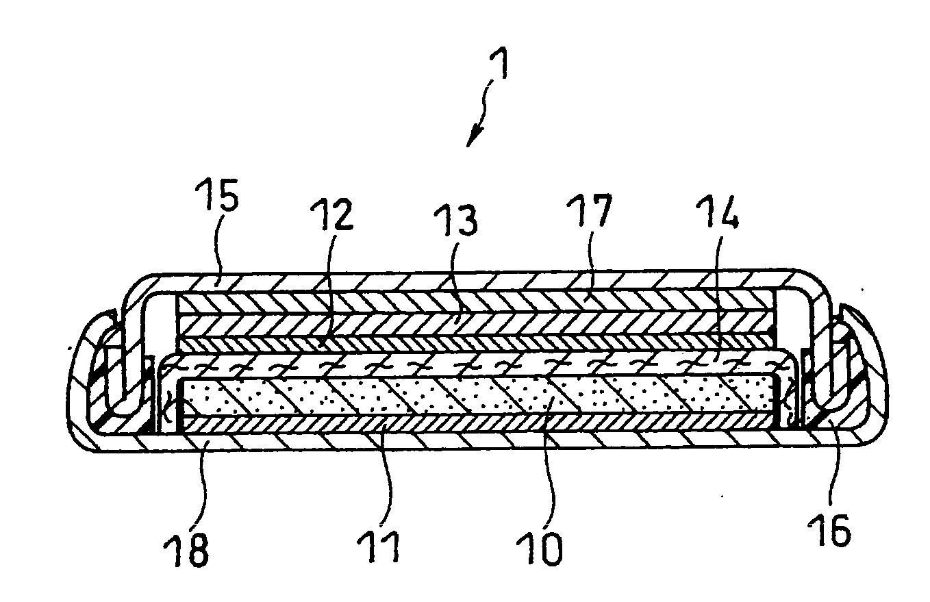
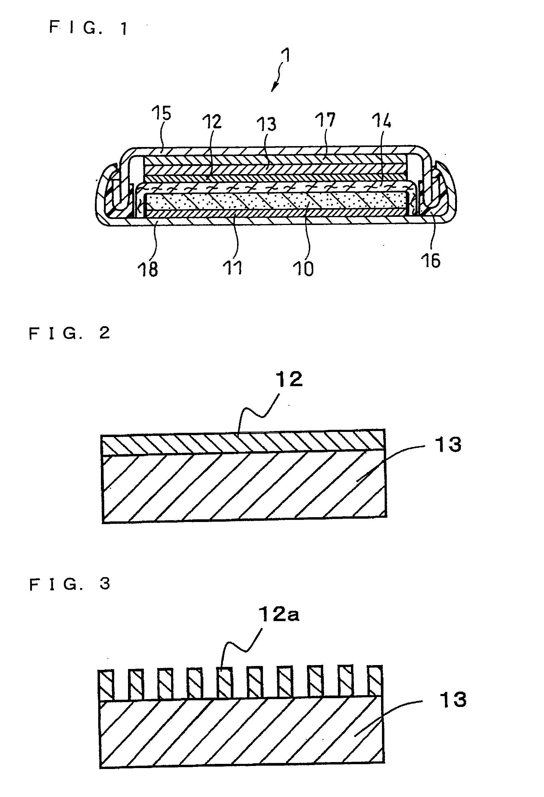
Disclosed is an electricity storage device which can be charged / discharged at high rate and have high output, high capacity and excellent repeating charge / discharge characteristics, although it uses a non-carbon material as a negative electrode active material. Specifically disclosed is an electricity storage device comprising: a positive electrode collector; a positive electrode disposed on the positive electrode collector and including a positive electrode active material which can reversibly absorb / desorb at least anions; a negative electrode collector; and a negative electrode disposed on the negative electrode collector and including a negative electrode active material which can substantially absorb / desorb lithium ions reversibly. The negative electrode active material is composed of at least one substance selected from the group consisting of silicon, a silicon-containing alloy, a silicon compound, tin, a tin-containing alloy, and a tin compound; and the negative electrode is formed as a thin film having a thickness of 10 μm or less.

Description

TECHNICAL FIELD[0001]The present invention relates to an electricity storage device that has high output, high capacity, and excellent repeated charge and discharge (hereinafter referred to as charge / discharge) life characteristics.BACKGROUND ART[0002]Conventionally, electricity storage devices capable of being charged / discharged are used as: a power supply for hybrid cars powered by using two types of energy being gasoline and electricity, and for various electronic equipments, particularly for mobile communications equipments, portable electronic equipments, and the like; an uninterruptible power supply; and the like. With the recent dissemination of hybrid cars and electronic devices, demand for enabling higher performance in electricity storage devices is becoming extremely high. In response to this demand, research and development related to electric double layer capacitors, which is one type of electricity storage device, are being actively pursued. Electric double layer capac...

Claims


Application Information

Patent Timeline
IPC IPC(8): H01M4/60H01M4/58H01G11/02H01G11/06H01G11/22H01G11/30H01G11/42H01G11/46H01G11/48H01G11/70H01M4/13H01M4/133H01M4/134H01M4/136H01M4/137H01M4/139H01M4/1393H01M4/1395H01M4/1397H01M4/1399H01M4/38H01M4/48H01M4/583H01M4/587H01M4/66H01M4/70H01M4/74H01M4/80H01M10/05H01M10/0525H01M10/0566H01M10/058H01M10/36
CPCH01M4/133Y02E60/13H01M4/1393H01M4/1395H01M4/382H01M4/483H01M4/587H01M4/64H01M4/70H01M10/0525H01M12/005H01M2004/021H01M2010/4292Y02E60/122Y02T10/7011Y02T10/7022H01G11/26H01G11/28H01G11/32H01G11/50H01M4/134H01G11/30H01G11/70H01M4/38H01M4/386H01M4/387H01M4/48H01M4/58H01M4/60H01M10/05H01G11/06Y02T10/70Y02E60/10Y02P70/50
Inventor HOJO, NOBUHIKOOHTSUKA, YUWATANABE, SHOICHIROHONDA, KAZUYOSHI
Owner PANASONIC CORP
Learn More