
Applicator instruments for controlling bleeding at surgical sites and methods therefor

Active Publication Date: 2009-10-01
ETHICON INC
View PDF49 Cites 18 Cited by
  • Summary
  • Abstract
  • Description
  • Claims
  • Application Information

AI Technical Summary

Benefits of technology

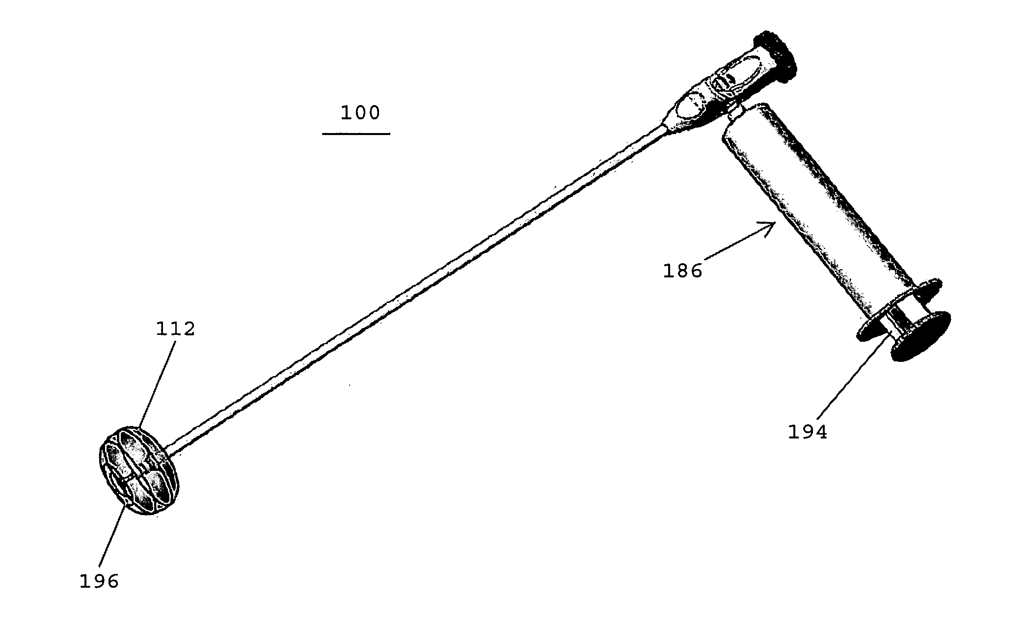
[0028]Although the present invention is not limited by any particular theory of operation, it is believed that the present invention provides numerous benefits over prior art instruments, systems, and methods. One advantage of the present invention is that the shape of an inflated balloon may be altered so as to maximize the surface area available for applying tamponade pressure to a deployed hemostat. The increased surface area and the flatter surface area allows for more efficient and enhanced tamponade pressure to be applied to the hemostats. This feature is particularly useful for applying pressure to topically applied hemostats.
[0029]In addition, in one embodiment, the present invention discloses an applicator instrument having a transparent balloon that enables medical personnel to observe a surgical site as tamponade pressure is applied to hemostats using the balloon.
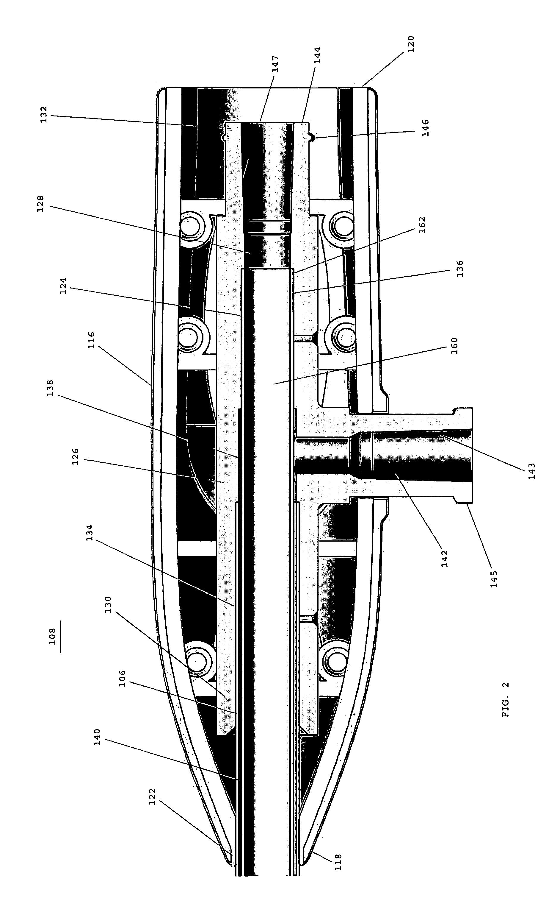
[0030]In one embodiment, the outer and inner shafts of the applicator instrument are not moveable, and the balloon does not change shape. After the balloon is inflated to a desired shape, either spherical or toroidal as described earlier, the fluid used to inflate the balloon is communicated between the outer diameter (OD) of the inner shaft and the inner diameter (ID) of the outer shaft. The lumen of the inner shaft may be in communication through the proximal handle of the device. The proximal end of the inner shaft may have a syringe connector means, such as a Luer connector, attached thereto. The Luer connector may be used to attach a syringe that dispenses a fluid (e.g. SURGIFLO) through the lumen of the inner shaft into a surgical cavity, with the balloon in either an inflated or deflated state. The lumen of the inner shaft may also be used to guide, support and allow passage of other fluid delivery systems, such as the EVICEL Fibrin Sealant having a 45 cm catheter delivery device. Moreover, a Luer cap or plug may be attached to the Luer connector to prevent surgical cavity insufflation gases from undesirably exiting through the instrument. In one embodiment, a stylet may be passed through and attached to the Luer connector. The stylet preferably has a length such that the tip of the stylet is in close proximity to the distal end of the lumen of the inner shaft. The distal tip of the stylet may have Velcro-like barbs, for the purpose of engaging and picking up and a textile based topically applied hemostat (TAH) as described herein.
[0031]In one embodiment, the applicator instrument may have only a single shaft, and the balloon may not change shape after it is inflated. In one embodiment, both the distal and proximal ends of the inflatable balloon are attached to the outer diameter (OD) of a single shaft. The proximal end of the shaft may have a hub connector secured thereto. A syringe having a flowable hemostat may be coupled to the hub connector for dispensing a flowable hemostat through a central lumen of the shaft.
[0032]In one embodiment, a user may physically hold the balloon inflation syringe plunger in the depressed position in order to keep the balloon inflated. The user may pull back on the syringe plunger to deflate or aspirate the balloon, or the syringe may have an axially aligned internal spring that is adapted to return the plunger to the extended position for automatically aspirating the balloon. In one embodiment, the spring may be axially aligned and be located between the proximal surface of the barrel's flange and the distal surface of the plunger's proximal flange.
[0033]In one embodiment, the syringe includes a locking ring that engages the outer surface of a cylindrical plunger to lock the plunger in place. When it is desired to move the plunger, the locking ring may be pushed toward the leading end of the syringe to release the plunger for movement. This embodiment may incorporate one or more of the features or method steps disclosed in commonly assigned U.S. patent application Ser. No. 12 / 049,849, entitled “APPLICATOR INSTRUMENTS FOR THE DELIVERY, DEPLOYMENT, AND TAMPONADE OF HEMOSTATS AND METHODS THEREFOR, filed Mar. 17, 2008, the disclosure of which is hereby incorporated by reference herein.

Problems solved by technology

The inserter device disclosed in the '395 patent, however, is not suitable for insertion through an endoscopic tube or trocar.

Method used


Image

  • Applicator instruments for controlling bleeding at surgical sites and methods therefor
  • Applicator instruments for controlling bleeding at surgical sites and methods therefor
  • Applicator instruments for controlling bleeding at surgical sites and methods therefor

Examples


Embodiment Construction

[0077]The invention disclosed herein is not limited in its application or use to the details of construction and arrangement of parts illustrated in the accompanying drawings and description. The illustrative embodiments of the invention may be implemented or incorporated in other embodiments, variations and modifications, and may be practiced or carried out in various ways.

[0078]The headings used herein are for organizational purposes only and are not meant to limit the scope of the description or the claims. As used throughout this application, the word “may” is used in a permissive sense (i.e., meaning having the potential to), rather than the mandatory sense (i.e., meaning must). Similarly, the words “include”, “including”, and “includes” mean including but not limited to. To facilitate understanding, like reference numerals have been used, where possible, to designate like elements common to the figures.

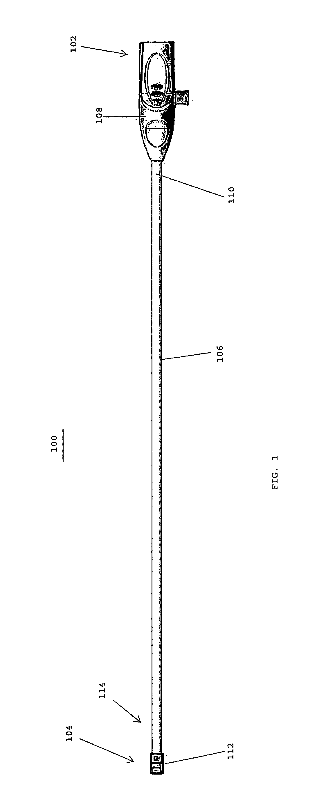
[0079]Referring to FIG. 1, in one embodiment, an instrument 100 for control...


PUM


Abstract

An instrument for controlling bleeding includes an outer shaft having a central lumen extending between proximal and distal ends thereof, and an inner shaft disposed within the central lumen of the outer shaft, the inner shaft having a central lumen extending between proximal and distal ends thereof. The instrument has an inflatable balloon with a proximal end secured to the outer shaft and a distal end that is inverted and secured to the inner shaft. In one embodiment, the balloon has a spherical shape when the outer and inner shafts are in a first position and a toroidal shape when the outer and inner shafts are in a second position. The instrument includes an actuator for discharging a flowable material from the central lumen. In one embodiment, the instrument includes a stylet having barb-like features to attach a hemostat to the distal end of the instrument.

Description

CROSS REFERENCE TO RELATED APPLICATIONS[0001]The present application is related to commonly assigned U.S. patent application Ser. No. 12 / 049,849, entitled “APPLICATOR INSTRUMENTS FOR THE DELIVERY, DEPLOYMENT, AND TAMPONADE OF HEMOSTATS AND METHODS THEREFOR,” filed Mar. 17, 2008, and U.S. patent application Ser. No. 12 / 049,869, entitled “APPLICATOR INSTRUMENTS HAVING PROTECTIVE CARRIERS FOR HEMOSTATS AND METHODS THEREFOR,” filed Mar. 17, 2008, the disclosures of which are hereby incorporated by reference herein.BACKGROUND OF THE INVENTION[0002]1. Field of the Invention[0003]The present application is generally related to controlling bleeding, and is more specifically related to systems, instruments, and methods used for the delivery, deployment, and tamponade of hemostats and flowable hemostats and sealants used for controlling bleeding at surgical sites.[0004]2. Description of the Related Art[0005]Medical textiles are used during surgical procedures to control bleeding, minimize blo...

Claims


Application Information

Patent Timeline
IPC IPC(8): A61M29/02A61F2/958
CPCA61B17/00491A61B17/12136A61B2017/00778A61B17/1204A61M25/1002A61M25/1006A61M2025/1015A61B2017/1205
Inventor GABEL, JONATHAN B.LIVINGSTON, JASON C.LOONEY, DWAYNE
Owner ETHICON INC
Learn More