Lens driving device and electronic equipment

Inactive Publication Date: 2009-10-08
SEIKO INSTR INC
View PDF7 Cites 5 Cited by
  • Summary
  • Abstract
  • Description
  • Claims
  • Application Information

AI Technical Summary

Benefits of technology

[0028]The electronic equipment of the present invention includes the inexpensive lens driving device improved in assembling performance and high in reliability. Thus, reliability can similarly be improved to achieve higher quality and lower costs.
[0029]According to the lens driving device of the present invention, any user can easily and surely perform assembling while the rotation of the nut is regulated, and assembling performance can be improved without damaging any components. Thus, the lens driving device ca

Problems solved by technology

First, in order to move the nut back and forth through rotating the lead screw, it is necessary to regulate the rotation of the nut by the rotation regulation unit. If rotation regulation is uncertain, the nut is rotated in accordance with rotation of the lead screw, disabling back-and-forth movement of the nut. Thus, when the lens driving device is assembled, combination of the nut with the rotation regulation unit has to be ensured

Method used


Image

  • Lens driving device and electronic equipment
  • Lens driving device and electronic equipment
  • Lens driving device and electronic equipment

Examples


Example

[0049]Referring to FIGS. 1 to 16, a preferred embodiment of the present invention is described below.

[0050]A lens driving device of this embodiment is mounted on electronic equipment such as a camera, a portable telephone with a camera, or a disk reader targeting a next-generation optical disk, and moves a lens used for photographing or reading data back and forth to adjust a position thereof, thereby performing focus adjustment.

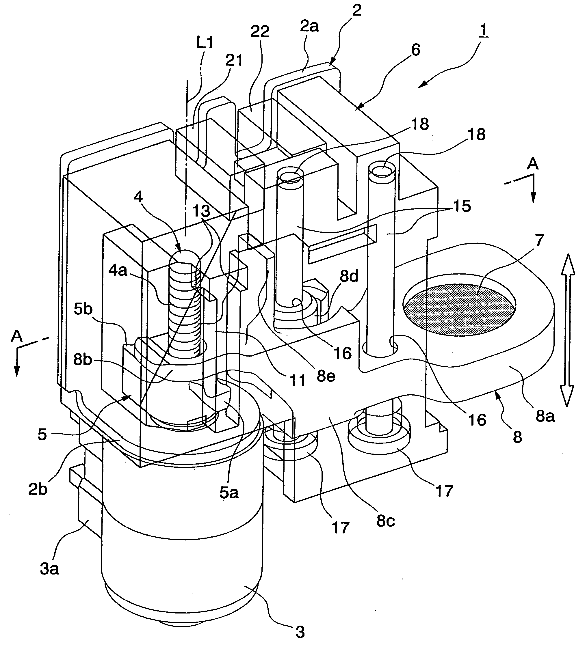
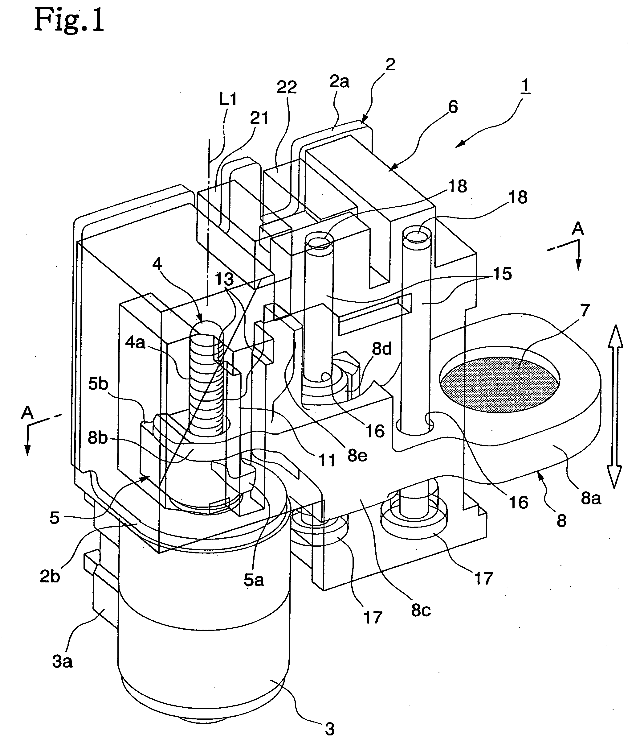
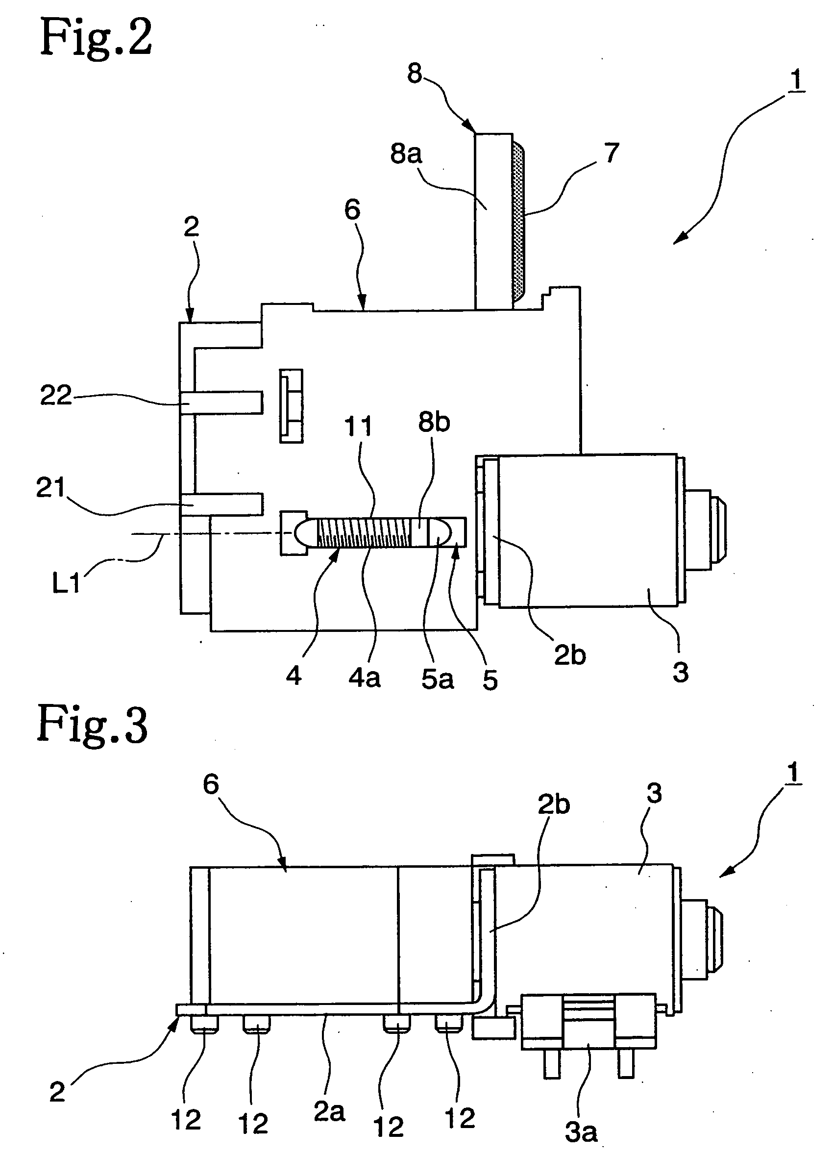
[0051]As schematically illustrated in FIGS. 1 to 5, a lens driving device 1 includes a motor 3 fixed to a plate 2, a lead screw 4 having its base end connected to the motor 3, a nut 5 threadingly engaged with the lead screw 4, a casing 6 detachably fixed to the plate 2, and a lens frame 8 for holding a lens 7. FIG. 1 illustrates a transparent state of the casing 6.

[0052]The plate 2 is made of a metal or plastic resin, and includes a plate main body 2a formed into a flat plate shape and a bent plate 2b bent by about 900 with respect to the plate main body 2a,...


PUM


Abstract

Provided is a lens driving device (1) including: a lead screw (4) connected to a motor fixed to a plate (2); a nut (5) which is threadingly engaged with the lead screw (4), and has a convex protruding portion (5a); a casing (6) fixed to the plate; a fitting groove (11) for fitting the protruding portion in the fitting groove (11) so as to regulate rotation of the nut, and movably guiding the protruding portion in a fitted state in a direction of an axial line (L1) to move the nut back and forth; and a lens frame (8) including a lens holding portion (8a) for holding a lens and an abutting portion (8b) abutting the nut, and formed so as to move in accordance with back-and-forth movement of the nut to move the lens back and forth in the direction of the axial line. At least one of the casing and the protruding portion has a tapered surface (13) formed so as to forcibly guide the protruding portion toward the fitting groove to gradually change to the fitted state. Thus, any user can easily and surely perform assembling while the rotation of the nut is regulated, and assembling performance is improved without damaging any components.

Description

BACKGROUND OF THE INVENTION[0001]1. Field of the Invention[0002]The present invention relates to a lens driving device for focusing or adjusting a focus (zoom) of a digital camera, a portable telephone with a camera, or a disk reader, and electronic equipment including the same.[0003]2. Description of the Related Art[0004]Conventionally, in electronic equipment such as a digital camera, a portable telephone with a camera, or a disk reader targeting a next-generation optical disk, focusing or focus adjustment has generally been performed by using a lens driving device to adjust a lens position.[0005]Various types of lens driving devices have been available, representative one of which adjusts a lens position by using a nut and a lead screw. The lens driving device of this type typically includes a lead screw rotated by a motor, a nut threadingly engaged with the lead screw, a lens frame provided to move back and forth along a guide shaft disposed in an optical axis direction in its a...

Claims


Application Information

Patent Timeline
IPC IPC(8): F16H37/16
CPCG02B7/023Y10T74/18048G02B7/08
Inventor TSUCHIYA, TADASHI
Owner SEIKO INSTR INC
Why Eureka
Try Eureka