Eureka AIR delivers breakthrough ideas for toughest innovation challenges, trusted by R&D personnel around the world.

Heat recovery device with self-cleaning

Active Publication Date: 2009-10-08
MEIKO MASCHENBAU
View PDF21 Cites 20 Cited by
  • Summary
  • Abstract
  • Description
  • Claims
  • Application Information

AI Technical Summary

Benefits of technology

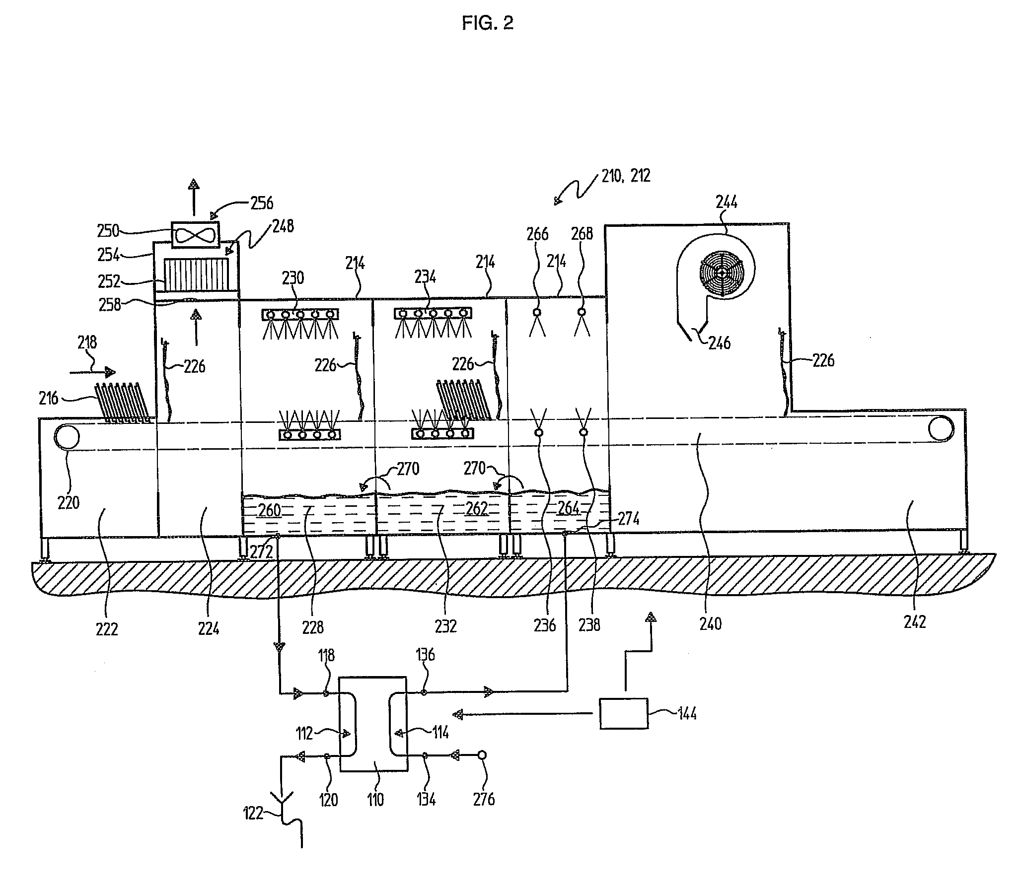
[0014]The invention is based on the basic idea that, in particular for use in heat recovery systems for recovering heat from waste water, fatty impurities can be eliminated by the brief introduction of heat into the otherwise cold heat exchanger surfaces. In the process, the impurities are melted or at least deformed and can thus be easily removed by, for example, the waste water flowing past the heat recovery device or through this heat recovery device. Cleaning can also be performed in this way for heat recovery devices used in other fluid media, for example heat recovery devices in exhaust-air streams of dishwashers, since molten impurities can, for example, be washed away more easily or can drain completely, for example, into a collection container or another disposal system.
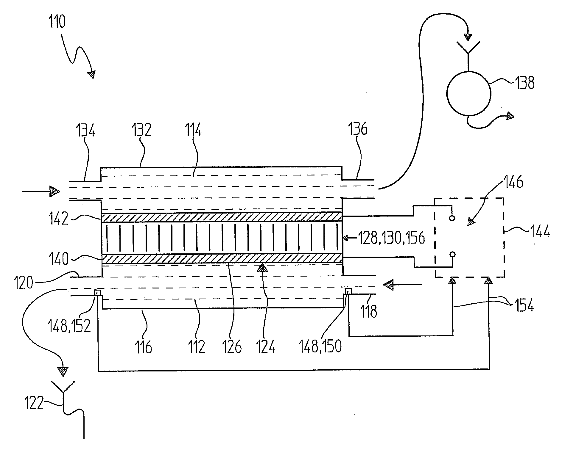
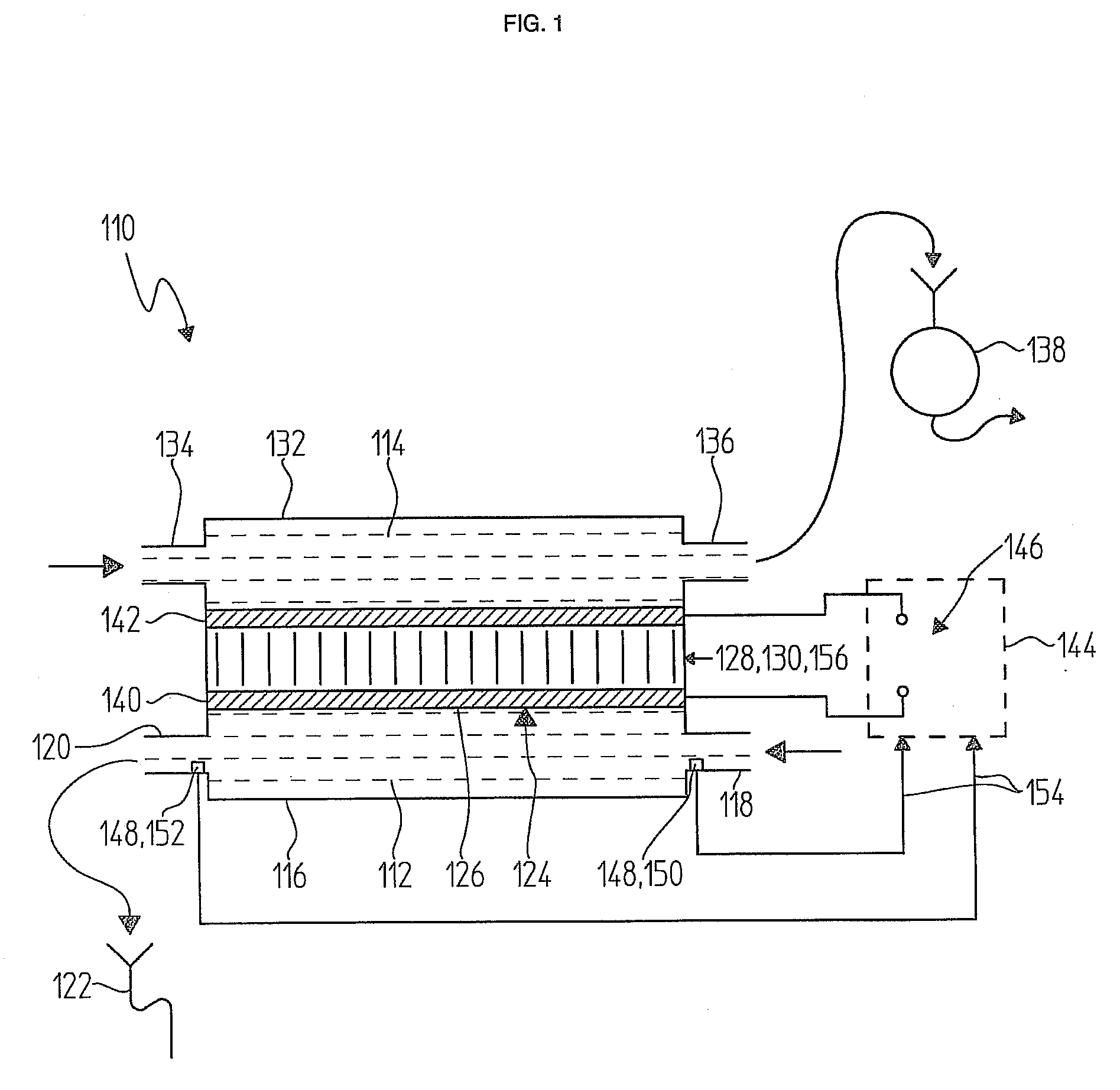
[0018]The heat recovery device further has at least one controller which is designed to carry out a self-cleaning process for the heat exchanger. As described above, the heat exchanger surface is briefly heated by means of the heating device, for example to the abovementioned temperatures, during the self-cleaning process. However, higher or lower temperatures are also possible, for example temperatures above 90° C. or 100° C. As described above, the layer of impurities is preferably melted or at least softened by the action of heat during the self-cleaning process for the heat exchanger, and so said layer of impurities can be removed more easily. Additional media, in particular the fluid medium itself, can then actually remove the impurity.
[0020]The proposed heat recovery device therefore permits rapid and efficient self-cleaning, without the operation of the appliance or a surrounding area in which the heat recovery device is used having to be influenced by the self-cleaning process. In particular, a washing mode of a dishwasher or another type of cleaning mode, for example, can be continued without interruption, with heat recovery being reduced or stopped only during the self-cleaning process. In this case, “brief” is to be understood as a self-cleaning process which is carried out for, for example, between 30 seconds and 3 hours, but preferably in the region of a few minutes (for example 1 to 30 minutes). However, shorter or longer self-cleaning processes are possible in principle and are intended to be covered by the term “brief”. The term “brief” therefore means only that the heating device is not operated continuously, so that the overall function of heat recovery is not significantly interrupted by the self-cleaning process.
[0022]Combination of the heat exchanger with the heat pump provides the considerable advantage that the comparatively low temperatures which usually occur during heat recovery can be compensated. Customary waste-water temperatures, for example, are therefore approximately 60° C. in the field of commercial dishwashers. Even in the event of complete transfer of this temperature to a transportation medium, for example a rinsing liquid, this temperature is generally not sufficient for expedient utilization in the dishwasher itself, and so additional heating would be required. By virtue of the interposition of a heat pump, the transportation medium, for example a cleaning fluid which is used in a cleaning appliance and is heated in advance by means of the heat drawn from the fluid medium, can preferably be heated to a target temperature, for example a temperature of between 80° C. and 90° C., which can be used, for example, in a rinsing process.
[0024]In this way, the advantages of the invention, namely self-cleaning by means of the brief introduction of heat and as a result the elimination of, in particular, fat impurities, can be combined with the advantages of heat pump coupling, by means of which the recovered thermal energy can be raised to a usable temperature level. Additional heating elements can be dispensed with in this case.
[0028]However, as an alternative or in addition to the said sensor principles, it is particularly preferred when at least two temperature sensors are used as dirt sensors. For example, the temperature sensors can be designed in such a way that they detect a temperature of the fluid medium before and after the medium flows through and / or across the heat exchanger. If the level of soiling on the heat exchanger plates rises, the efficiency of the heat exchanger falls, and the temperature difference before and after the medium flows through the heat exchanger falls. It is therefore possible, in this way, to likewise effectively detect dirt, and a self-cleaning process can be initiated, for example, automatically.

Problems solved by technology

In many instances, a considerable quantity of thermal energy has to be applied in a cleaning appliance of this type.
This outlay on thermal energy can be considerable in the commercial sector in particular, and so, for example, heating capacities can make a considerable contribution to the overall operating costs of the cleaning appliance.
In practice however, conventional heat recovery devices, in particular heat exchangers, have some disadvantages.
For example, one considerable disadvantage is, in particular, that heat exchangers which are used to recover heat from exhaust air or waste water have soiling effects.
However, these servicing operations are undesirable and expensive since, in particular, continuous operation for commercial use has to be interrupted for such servicing operations.
In addition, a large number of heat exchangers are of such complex construction that straightforward and satisfactory cleaning cannot be carried out on site in all cases.
However, the heat exchangers or heat recovery devices with self-cleaning apparatuses which are known from the prior art, in particular from DE 10 2005 050 305 B3, have considerable disadvantages, in particular for use in commercial dishwashers, but also in other fields of heat recovery.
In particular, the spray nozzle principle of self-cleaning cannot be used for heat exchangers which are to be used in the field of heat recovery from waste water.
This formation of layers of fat on the heat exchanger surfaces which occurs as a matter of principle adversely affects heat transfer and therefore adversely affects functioning of the heat recovery devices.
The described spray methods, for example the self-cleaning described in DE 10 2005 050 305 B3, can remove hardly any such fatty impurities in practice, or the use of aggressive detergents is required, and this would again lead to increased pollution of the environment.
The problem is even greater in the case of heat recovery devices which are to be used in waste-water systems since it is extremely difficult here to wash the heat recovery device, in particular the heat exchanger plates, with a cleaning fluid which dissolves fats and other impurities in practice.

Method used


Image

  • Heat recovery device with self-cleaning
  • Heat recovery device with self-cleaning
  • Heat recovery device with self-cleaning

Examples


Embodiment Construction

[0041]FIG. 1 illustrates one possible exemplary embodiment of a heat recovery device 110 according to the invention. This heat recovery device 110, which could be used in cleaning appliances for example, serves to recover heat from a fluid medium 112, of which it is assumed in the text which follows that it should be a spent cleaning fluid, in particular washing water containing cleaning additives and impurities. The recovered heat should be transferred to a transportation medium 114. To this end, the heat recovery device comprises a first chamber 116 with a first inlet 118 and a first outlet 120, it being possible for the first inlet 118 to be connected, for example, to an outflow of a dishwasher, and it being possible for the first outlet 120 to be connected, for example, to an outflow 122. In this case, the first chamber 116 is illustrated only symbolically in FIG. 1 and here comprises, for example, an expanded chamber, but with other designs also being possible, for example s-sh...


PUM


Abstract

A heat recovery device is provided for recovering thermal energy from a fluid medium, in particular for use in a waste-water system of a dishwasher. The heat recovery device comprises at least one heat exchanger with at least one heat exchanger surface. The heat recovery device further comprises at least one heating device, which is thermally coupled to the heat exchanger surface, and also at least one controller. The controller is designed to carry out a self-cleaning process for the heat exchanger, with the heat exchanger surface being briefly heated by means of the heating device during the self-cleaning process.

Description

[0001]This nonprovisional application claims priority under 35 U.S.C. § 119(a) to German Patent Application No.DE 10 2008 015 798.8, which was filed in Germany on Mar. 26, 2008, and which is herein incorporated by reference.BACKGROUND OF THE INVENTION[0002]1. Field of the Invention[0003]The invention relates to a heat recovery device for recovering thermal energy from a fluid medium. The invention further relates to a cleaning appliance which comprises a heat recovery device according to the invention, and also to a method for recovering thermal energy from a fluid medium. Such heat recovery devices and methods are used, in particular, in the field of commercial dishwashing in order to recover heat from waste water and / or exhaust air on a large scale. However, such heat recovery devices can also be used in other fields of technology.[0004]2. Description of the Background Art[0005]Cleaning appliances by means of which various types of washware can be cleaned with different objectives...

Claims


Application Information

Patent Timeline
IPC IPC(8): A47L15/42F25B21/04F25B29/00G05D23/00F28G13/00
CPCA47L15/241A47L15/247A47L15/4291A47L15/485Y02B30/52F28D21/0012F28G13/005F28G15/003Y02B30/566F25B21/04Y02B30/56Y02A20/30
Inventor GAUS, BRUNOKUPETZ, JOACHIMLEHMANN, DENISNAEGER, THOMASPEUKERT, THOMASSCHNEIDER, VERA
Owner MEIKO MASCHENBAU
Why Eureka
Eureka Blog
Learn More