Predistortion methods and apparatus for polar modulation transmitters

a transmitter and polar modulation technology, applied in the field of distortion in radio frequency transmitters, can solve the problems of large am/pm distortion, undetectable distortion of signals, and difficulty in meeting noise specifications set forth by wireless communication standards, and achieve the effect of less memory

Active Publication Date: 2009-10-08
PANASONIC CORP
View PDF8 Cites 47 Cited by
  • Summary
  • Abstract
  • Description
  • Claims
  • Application Information

AI Technical Summary

Benefits of technology

[0014]According to one aspect of the invention, the envelope component signal is scaled and/or offset by average-power-level-dependent pre predistortion scale and offset parameters before predistortion is applied to the envelope component signal. Scaling and/or offsetting the envelope component signal afford(s) the ability to share the AM/AM and AM/PM predistortion coefficients of the predistortion LUT over the plurality of average power levels. The ability to share the sa

Problems solved by technology

However, when it is operated in its nonlinear region, the PA 114 undesirably distorts the signals it amplifies.
Generally, the larger the amplitude of the leaked signal is relative to the amplitude of the amplitude modulated power supply signal, the larger the amount of AM/PM distortion.
AM/AM and AM/PM distortion can make it difficult to comply with noise specifications set forth by wireless communications standards.
As will be appreciated by those of ordinary skill in the art, this distortion characterization process can be very time consuming, particularly when there a

Method used


Image

  • Predistortion methods and apparatus for polar modulation transmitters
  • Predistortion methods and apparatus for polar modulation transmitters
  • Predistortion methods and apparatus for polar modulation transmitters

Examples


Embodiment Construction

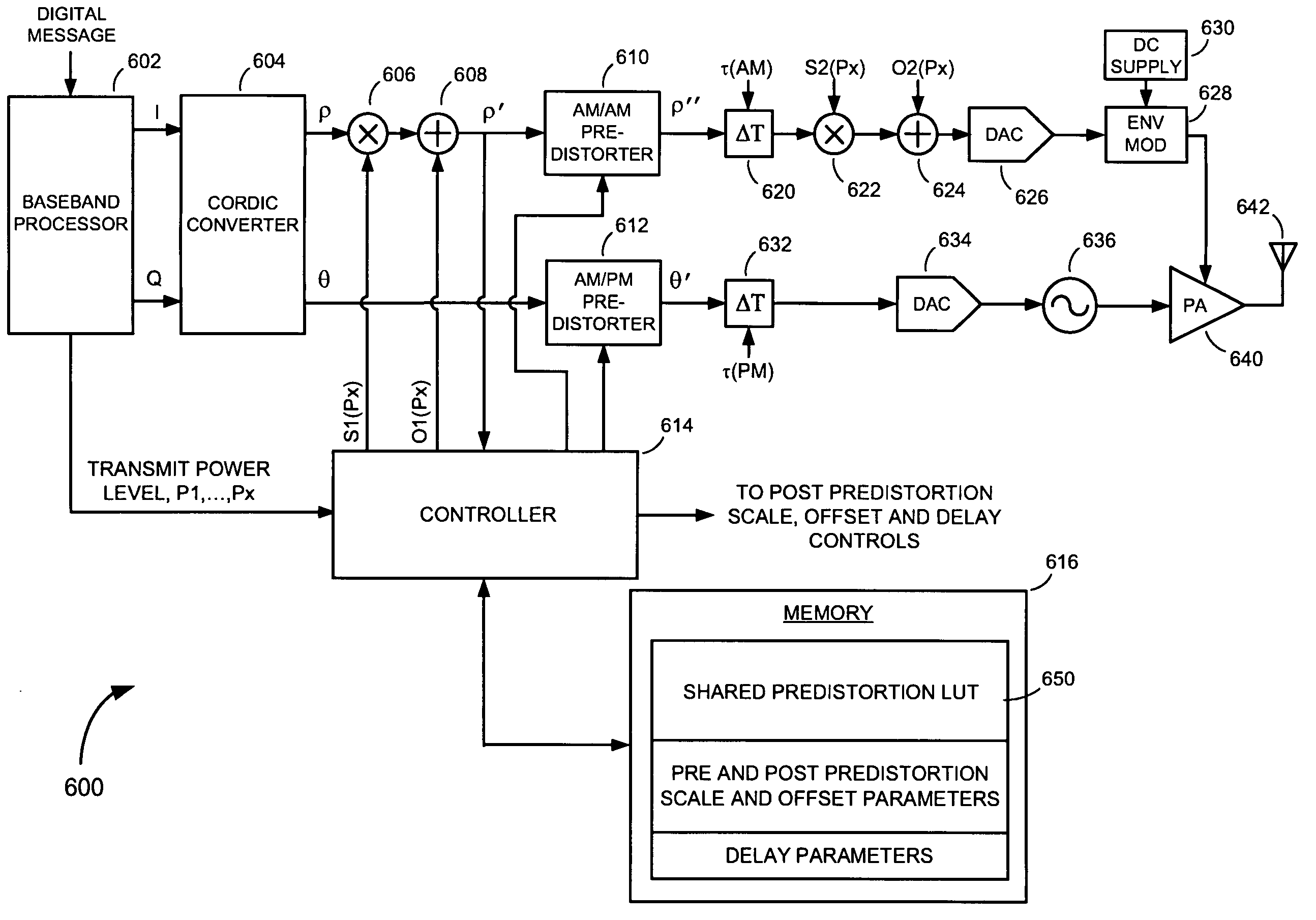
[0033]Referring to FIG. 6, there is shown a polar modulation transmitter 600, according to an embodiment of the present invention. The polar modulation transmitter 600 includes a baseband processor 602; a CORDIC converter 604; an AM / AM predistorter 610 disposed in an amplitude path; a first multiplier 606 and a first summer 608 coupled between an output of the CORDIC converter 604 and an input of the AM / AM predistorter 610 in the amplitude path; an AM / PM predistorter 612 disposed in a phase path; a controller 614; and a memory 616 that is configured to store, among other things, a predistortion LUT 650. Following the AM / AM predistorter 610 in the amplitude path is an amplitude path delay element 620; a second multiplier 622; a second summer 624; an amplitude path digital to analog converter DAC 626; and an envelope modulator 628. Following the AM / PM predistorter 612 in the phase path is a phase path delay element 632; a phase path DAC 634, and an RF oscillator 636. An output of the ...


PUM


Abstract

Methods and apparatus for predistorting signals in a polar modulation transmitter. An exemplary method includes predistorting an envelope component signal in an amplitude path of a polar modulation transmitter according to a set of AM/AM predistortion coefficients, and predistorting a phase component signal in a phase path of the polar modulation transmitter according to a set of AM/PM predistortion coefficients. The AM/AM and AM/PM predistortion coefficients are stored in a memory in the form of a look up table (LUT). The envelope component signal is scaled and/or offset, before predistortion is applied, by an amount dependent upon which average power level of a plurality of average power levels the power amplifier of the polar modulation transmitter is configured to operate. Scaling and/or offsetting the envelope component signal prior to applying predistortion affords the ability to share the AM/AM and AM/PM predistortion coefficients of the predistortion LUT over the plurality of average power levels.

Description

FIELD OF THE INVENTION[0001]The present invention relates to distortion in radio frequency transmitters. More specifically, the present invention relates to methods and apparatus for countering power amplifier induced distortion in polar modulation transmitters.BACKGROUND OF THE INVENTION[0002]The polar modulation transmitter is a type of radio frequency (RF) transmitter commonly used in wireless communications. The principal elements of a polar modulation transmitter 100 are shown in FIG. 1. They include a baseband processor 102; a COordinate Rotation DIgital Computer converter (CORDIC) 104; an amplitude path digital-to-analog converter (DAC) 106 and an envelope modulator 108 in an amplitude path; a phase path DAC 110 and an RF oscillator 112 in a phase path; a power amplifier (PA) 114; and an antenna 116.[0003]During operation, the baseband processor 102 generates digital in-phase (I) and quadrature phase (Q) signals from a digital message to be transmitted. The CORDIC converter 1...

Claims


Application Information

Patent Timeline
IPC IPC(8): H04L25/49
CPCH03F1/3241H04L27/367H04L27/361H03F1/3282
Inventor LEE, WAYNE S.WONG, TONY L.EVANS, HERB
Owner PANASONIC CORP
Why Eureka
Try Eureka