In-vivo optical imaging method including analysis of dynamic images

a dynamic image and optical imaging technology, applied in the field of optical molecular imaging methods for imaging animals, can solve the problems of difficult identification of signals by host organs, difficult localization, quantification, and many challenges of in-vivo optical molecular imaging, and achieve the effect of improving the generated image of a targeted region

Active Publication Date: 2009-10-08
THE GENERAL HOSPITAL CORP
View PDF61 Cites 40 Cited by
  • Summary
  • Abstract
  • Description
  • Claims
  • Application Information

AI Technical Summary

Benefits of technology

[0020]As used herein, animal is intended to encompass humans. Further, as used herein, structures refer to any of a broad category of items which can be differentiated in the image data sets, including for example organs, lymph nodes, tumors, functional structures, blood vessel networks, disease perimeters, and so forth. This approach takes advantage of the fact that various structures play different roles in circulating, metabolizing, or retaining an optical contrast substance, and an evaluation of the dynamics thereof provides useful information to identify these structures. In other words, various structures will exhibit individual distinctive time courses of the light emitted (or absorbed) due to the optical contrast substance. By evaluating these dynamics in the animal, various different structures can be identified, and the generated image of a targeted region can be improved over what is shown in an acquired image.

Problems solved by technology

However, in-vivo optical molecular imaging presents many challenges.
The main challenge is overcoming the effects of light scatter and absorption.
For example, when a fluorescent or luminescent dye is used to label specific cells, because the cells can be located deep within the body, the light emitted from them will undergo optical scattering because of intervening matter, which is more problematic the deeper the labeled cells are within the body.
Thus, unless the labeled cells are located near the outer surface of the animal, the scatter and absorption of light distorts and attenuates the signals emanating therefrom such that the localization, quantification, and host organ identification of the signals can be very difficult.
These effects can distort the apparent shape and location of these targeted labeled cells.
However, for transplanted cancer cells, xenografts often do not resemble the human disease, as these cells are often surrounded by a pseudo-capsule, have limited chances to invade major anatomical structures, and rarely spread metastasis.
Another problem associated with the use of fluorescent and luminescent molecular probes is that these are generally designed such that measurable light signals emanate from the labeled cells, with little or no detectable signals emanating from adjacent tissue or organs, so that the localization of the labeled cells is often uncertain.
In the absence of a non-invasive tool for verifying the anatomical location thereof, scientists are limited to ex-vivo histological examination of the labeled cells.
This can significantly increase study cost and time, and can degrade data owing to inter-animal variability.
Further, auto-fluorescence and non-specific labeling within the body confounds attempts to identify the true location of labeled cells.
However, such systems are highly complex, expensive, and still suffer from a lack of landmark anatomical structures to allow the actual anatomical location of the labeled cells to be identified.
While the IVIS Imaging System offers a generic computerized 3D mouse anatomical atlas to overlay with acquired image data to aid in organ identification, matching generic anatomy to each individual mouse is not always accurate and is highly sensitive to mouse age, size, repositioning, and any distortions within the optical images.
Such systems significantly increase the cost and complexity of the imaging process, especially when simultaneous image acquisition is attempted.
In addition, x-ray contrast of bone and the non-specific contrast of ultrasound will not provide good delineation of the internal soft tissue organs.
Since the imaging radiation and geometries are also different between modalities, co-registration with the optical images is problematic.

Method used


Image

  • In-vivo optical imaging method including analysis of dynamic images
  • In-vivo optical imaging method including analysis of dynamic images
  • In-vivo optical imaging method including analysis of dynamic images

Examples


Embodiment Construction

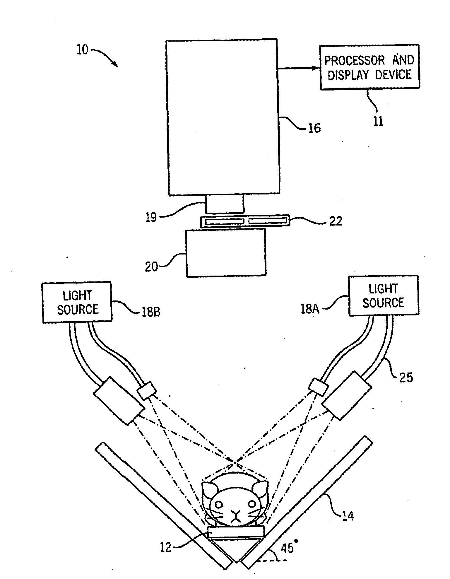
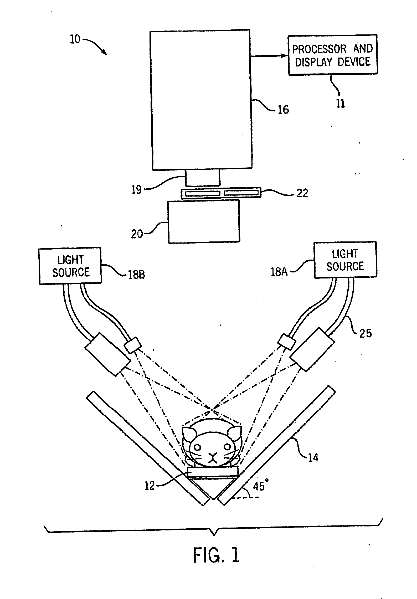
[0032]FIG. 1 illustrates one embodiment of a fluorescent dynamic optical imaging system 10 for imaging small animals such as mice. The imaging system 10 includes an optical detector 16 which is operable to acquire various images of the mouse. The imaging system 10 also includes a processor and display device 11 which is operable to generate and display other images of the mouse. These generated images can include an image of a targeted region, an anatomical image map which includes anatomical structures of the mouse, or a combined image of an anatomical image map and a targeted region, which shows a targeted region localized with respect to the anatomical structures. Both the acquired and generated images can be displayed on the display device 11.

[0033]Briefly, at least one optical contrast substance in the mouse is imaged with the imaging system 10 to acquire a time series of image data sets which are analyzed using the dynamics of the optical contrast substance to identify various...


PUM


Abstract

In-vivo optical molecular imaging methods for producing an image of an animal are described. A time series of image data sets of an optical contrast substance in the animal is acquired using an optical detector Each image data set is obtained at a selected time and has the same plurality of pixels, with each pixel having an associated value. The image data sets are analyzed to identify a plurality of distinctive time courses, and respective pixel sets are determined from the plurality of pixels which correspond to each of the time courses. In one embodiment, each pixel set is associated with an identified anatomical or other structure, and an anatomical image map of the animal can be generated which includes one or more of the anatomical structures.

Description

CROSS REFERENCES TO RELATED APPLICATIONS[0001]This application is based on U.S. provisional patent application Ser. No. 60 / 809,860, filed Jun. 1, 2006 and titled “Method and Device for Identification of Organ Location in Molecular Imaging”, Ser. No. 60 / 809,861, filed on Jun. 1, 2006, and Ser. No. 60 / 897,259, filed on Jan. 24, 2007, and titled “Method and Device for Identification of Organ Location in Molecular Imaging”.FIELD OF THE INVENTION[0002]The invention relates to an optical molecular imaging method for imaging animals including the acquisition of an in-vivo time series of images of at least one optical contrast substance, and the analysis of those images.BACKGROUND OF THE INVENTION[0003]In-vivo molecular imaging is a rapidly advancing field, impacting drug development and testing, research into disease processes, and potentially clinical diagnostic imaging. Optical molecular imaging is a method in which an optical contrast substance is introduced to or activated within an an...

Claims


Application Information

Patent Timeline
Patent Type & Authority Applications(United States)
IPC IPC(8): A61K49/00G06T7/00
CPCA61B5/0059A61B5/415A61B2503/40A61K49/0017A61B5/418
Inventor HILLMAN, ELIZABETH M.C.
Owner THE GENERAL HOSPITAL CORP
Why Eureka
Try Eureka