Fuel cell system and method of scavenging fuel cell system

Inactive Publication Date: 2009-10-08
HONDA MOTOR CO LTD
View PDF2 Cites 7 Cited by
  • Summary
  • Abstract
  • Description
  • Claims
  • Application Information

AI Technical Summary

Benefits of technology

[0028]In this case, since part of the generated water can be discharged using the scavenging gas when the deterioration countermeasure scavenging step is executed, it is possible to reduce the flow volume to match the flow volume of the scavenging gas necessary to discharge the generated water already discharged at the time of the succeeding sub-zero countermeasure scavenging step. Accordingly, it is possible to reduce the energy necessary for the sub-zero countermeasure scaven

Problems solved by technology

Therefore there is a problem in that it takes tim

Method used


Image

  • Fuel cell system and method of scavenging fuel cell system
  • Fuel cell system and method of scavenging fuel cell system
  • Fuel cell system and method of scavenging fuel cell system

Examples


Example

[0036]Next is a description of an embodiment of the present invention based on FIG. 1 to FIG. 4. In the present embodiment, a case will be described in which a fuel cell system is installed in a vehicle.

(Fuel Cell System)

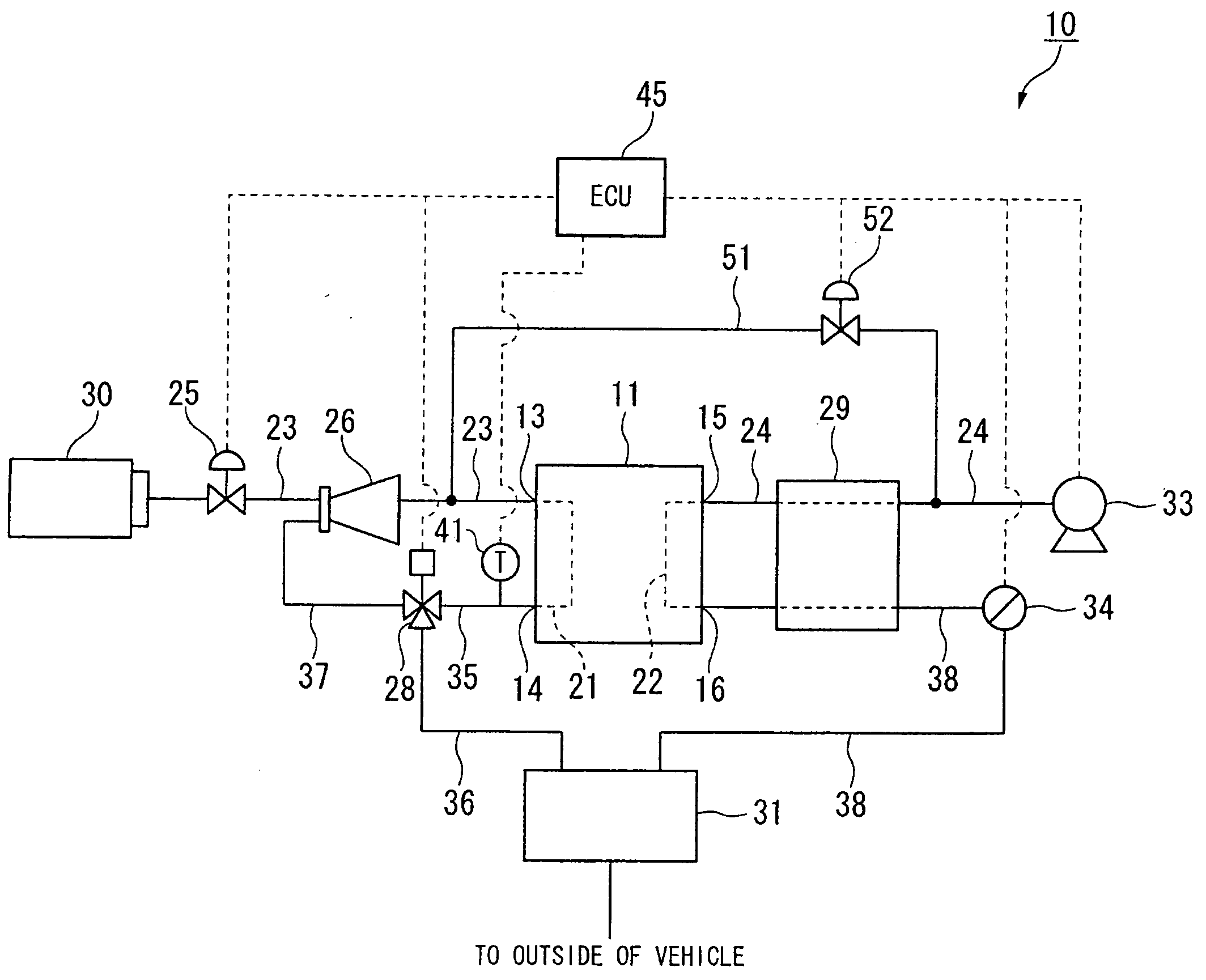
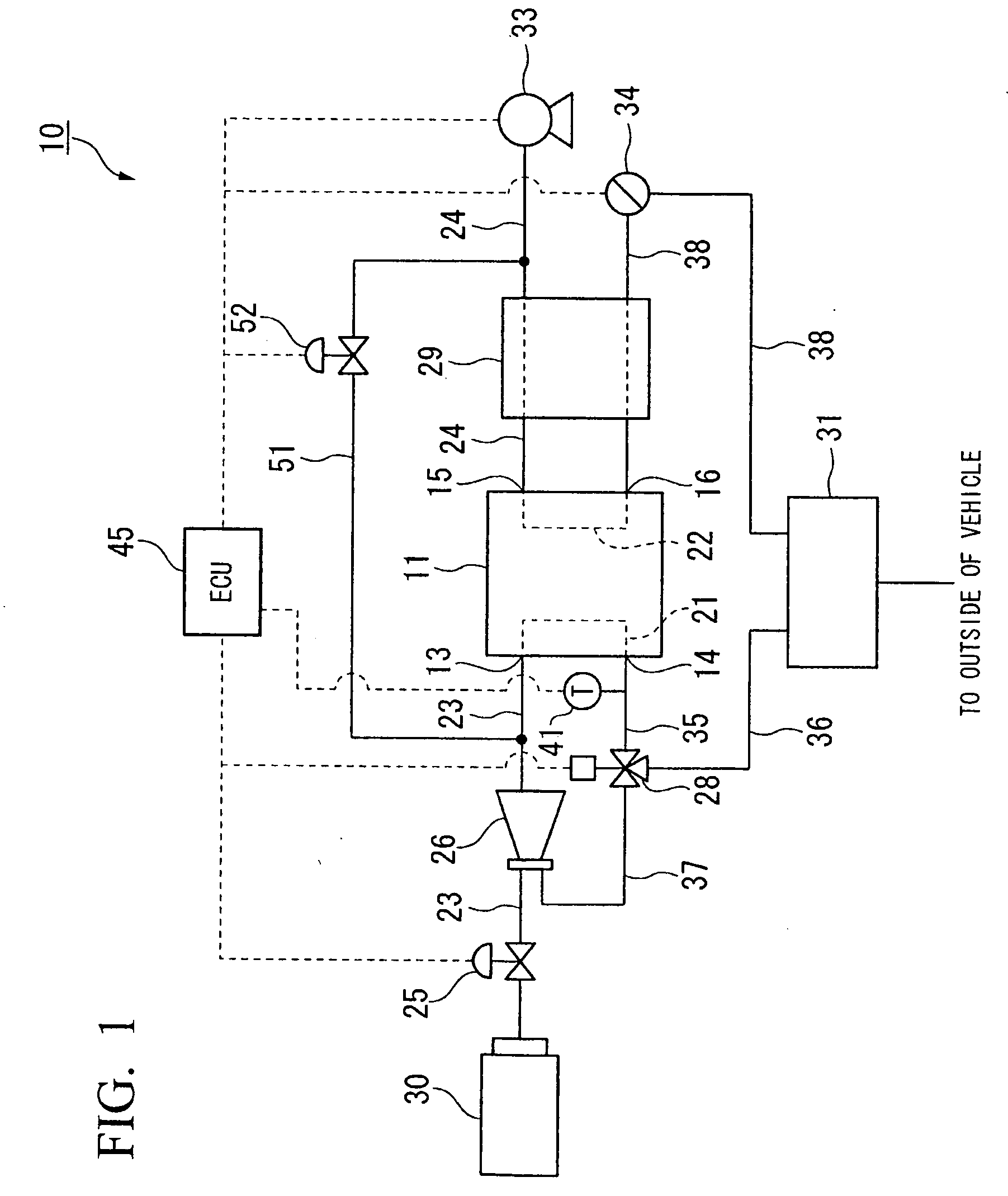
[0037]FIG. 1 is a schematic structural diagram of a fuel cell system.

[0038]As shown in FIG. 1, a fuel cell 11 of a fuel cell system 10 is a solid polymeric membrane type fuel cell, which generates electric power by an electrochemical reaction with a fuel gas such as hydrogen gas and an oxidant gas such as air. A fuel gas supply pipe 23 is connected to a fuel gas supply communicating opening 13 (entry end of a fuel gas channel 21) formed in the fuel cell 11, and a hydrogen tank 30 is connected to its upstream end. Furthermore, an oxidant gas supply pipe 24 is connected to an oxidant gas supply communicating opening 15 (entry end of an oxidant gas channel 22) formed in the fuel cell 11, and an air compressor 33 is connected to its upstream end. In addition, an anode o...


PUM


Abstract

A fuel cell system is provided with a fuel cell that supplies fuel gas to an anode electrode and that supplies oxidant gas to a cathode electrode to generate electric power; a scavenging gas supply device that scavenges the inside of the fuel cell; a temperature detection device that detects a temperature of the inside of the fuel cell; a deterioration countermeasure scavenging device that executes deterioration countermeasure scavenging by the scavenging gas supply device and replaces the accumulated gas accumulated in the anode electrode with the scavenging gas; and a sub-zero countermeasure scavenging device that executes sub-zero countermeasure scavenging with a greater flow volume than the scavenging gas supplied during the deterioration countermeasure scavenging and to discharge the generated water in the inside of the fuel cell.

Description

BACKGROUND OF THE INVENTION[0001]Priority is claimed on Japanese Patent Application No. 2008-100602, filed on Apr. 8, 2008, the contents of which are incorporated herein by reference.FIELD OF THE INVENTION[0002]The present invention relates to a fuel cell system and a method of scavenging a fuel cell system.DESCRIPTION OF THE RELATED ART[0003]Conventionally, as a fuel cell which is installed for example in a vehicle, a fuel cell stack (referred to hereunder as a fuel cell) which is stacked by a plurality of unit fuel cell (referred to hereunder as a unit cell) is known. In the fuel cell, the unit cell has a flat shape and is formed by arranging a pair of separators on the two sides of a membrane electrode structure. The membrane electrode structure is formed by sandwiching a solid polymer electrolyte membrane from two sides by an anode electrode and a cathode electrode. In such a fuel cell, hydrogen gas is supplied between the anode electrode and the separator as a fuel gas, and air...

Claims


Application Information

Patent Timeline
IPC IPC(8): H01M8/04H01M2/02
CPCH01M8/04007H01M8/04231H01M8/04253Y02E60/50H01M8/04753H01M8/04761H01M8/04783H01M8/04343
Inventor MATSUMOTO, YUJIUEDA, KENICHIROMIYATA, KOICHIRO
Owner HONDA MOTOR CO LTD
Why Eureka
Try Eureka