Fuel cell heater

a fuel cell and heater technology, applied in the field of heaters, can solve the problems of insufficient primary heat output of discarded heat, insufficient electrical wattage of conventional fuel cell generators, and inconvenient use of fuel cell electrical output to augment the rejected heat by resistive heating, etc., to achieve better and more advantageous overall results

Inactive Publication Date: 2009-10-08
HDT EXPEDITIONARY SYST INC
View PDF16 Cites 6 Cited by
  • Summary
  • Abstract
  • Description
  • Claims
  • Application Information

AI Technical Summary

Benefits of technology

[0029]According to another aspect of the present disclosure, a self-powered space heater comprises a fan for generating an air flow and a burner positioned downstream of the fan and communicating therewith for producing a hot gas. A first fuel cell assembly is operatively connected to the burner for receiving the hot gas produced by the burner. A second fuel cell assembly is operatively connected to the burner for receiving hot gas produced by the burner. The second fuel cell assembly is positioned in series with the first fuel cell assembly. The first and second fuel cell assemblies provide electrical energy to operate the space heater. A heat exchanger is positioned downstream of the first and second fuel cell assemblies and provides heat for an associated enclosure. A thermal output used of the burner for space heating exceeds a thermal input required for power generation.

Problems solved by technology

Even though fuel cell generators are being integrated into CHP for home or business use, the waste heat output is not sufficient to be used for primary heat but can be used for low level heating.
Conventional fuel cell generators cannot produce sufficient electrical wattage during high building demand periods.
Using the fuel cell electrical output to augment the rejected heat by using resistive heating can be counterproductive due to having less electrical power available for building demands.
The ability of using a fuel cell as a primary or single source space heater is limited due to this efficiency.
However, this type of fuel cell integration, when used for primary heating, provides insufficient waste heat.
Using the rejected heat and power output of a fuel cell for primary space heating is not practical due to the increased cost, size and weight of a cogenerated fuel cell that is sized to produce electrical resistive and combustion heat outputs sufficient for total space heating requirements.
As is evident from the above prior art, space heating by using a single burner for the combustion is insufficient as a provider of primary building heat, even if combined with the teachings of integrating burners and combustors with a fuel cell.
Also lacking in the prior art is the ability to switch between available fielded fuels, such as diesel, kerosene, DF-A, Jet-A, JP-5 and JP-8.
The additional concern of combustion inefficiencies with altitude changes renders these approaches ineffective for a space heater application.
Further, a deficiency of current fuel cell designs that operate on diesel, bio fuels and kerosene when used in a co-generation primary heater application is the required time from a cold start to rated power and heat output.
Component warming before fuel cell operation and heat output can be a lengthy process delaying sufficient hot air output.
Another deficiency of current fuel cell designs when used in a co-generation primary heater application becomes apparent when the application requires a higher heat output than is available from capturing all of the fuel cell's waste heat and electrical output.
Sufficient resistive heating required for space heating will increase the heat output, but will also increase cost, weight and size of the fuel cell.
Weight and size become excessive when compared to a current 35,000 BTU self-powered thermoelectric heater.
Yet another deficiency of current fuel cell designs when used in a co-generation primary heater application is the burner used for starting, reforming or exhaust gas management.
The burner, which is sized and directly coupled to the fuel cell component for fuel cell operation, has the inability to increase combustion for additional space heating.
Another deficiency is the inability to operate in cold temperatures of −60° F. This severe cold operation is a standard requirement for shelter heating.
Current fuel cell heat recovery methods are overly efficient, not addressing dew point condensation during severe cold start up and subsequent ice buildup in heat recovery and exhaust systems during severe cold starting and operation.
Another deficiency is that current fuel cell component integration requires thermal coupling of components for operation, such as a reformer being integrated within the same hot zone as a cell stack.
This makes repair in the field difficult requiring subcomponent removal to gain access, remove and replace components such as the reformer.
Taken individually or as a whole, the prior art fails to provide an overall design for a practically implemented forced air, multi-fueled warm air heating system that provides space heating for soft and hard wall shelters while simultaneously operating a fuel cell that provides electrical power for safe and efficient heater operation.

Method used


Image

  • Fuel cell heater
  • Fuel cell heater
  • Fuel cell heater

Examples


Embodiment Construction

[0045]It should, of course, be understood that the description and drawings herein are merely illustrative and that various modifications and changes can be made in the structures disclosed without departing from this disclosure. Like numerals refer to like parts throughout the several views. It will also be appreciated that the various identified components of the space heater disclosed herein are merely terms of art that may vary from one manufacturer to another and should not be deemed to limit the present disclosure.

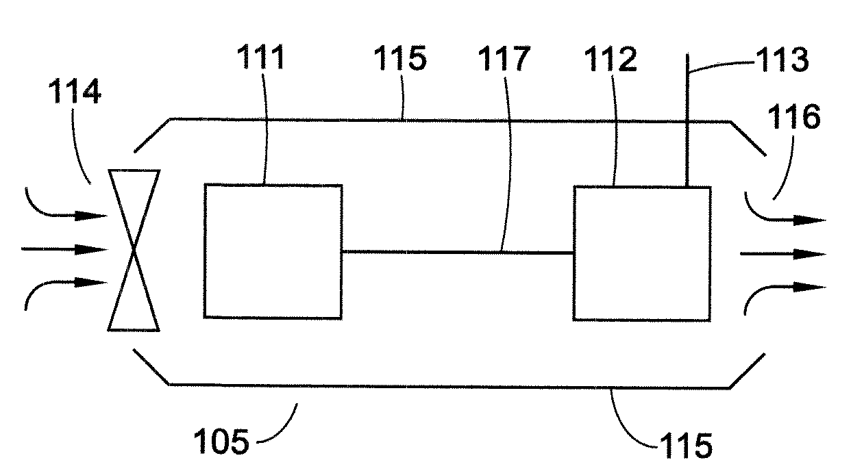
[0046]With reference to FIG. 1, a schematic of a conventional fuel fired, hot air space heater 105 is illustrated. The heater is the type which that would operate on externally supplied electrical power from a local power grid or a generator. The heater 105 includes an enclosure 115 for housing a burner 111 operably connected to a heat exchanger 112. A fan 114 is provided at an inlet of the enclosure for generating air flow through the enclosure. The enclosure 115 is...


PUM


Abstract

A self-powered space heater comprises a fan, a burner, a heat exchanger and an fuel cell assembly. The fan generates an air flow. The burner is positioned downstream of the fan and communicates therewith. The burner produces a hot gas. The heat exchanger is positioned downstream of the burner and is operatively connected therewith for receiving at least some of the hot gas. The heat exchanger provides heat for an associated enclosure. The fuel cell assembly provides electrical energy to operate the space heater. The fuel cell assembly is operatively connected to the burner for receiving at least some of the hot gas. The fuel cell assembly includes a fuel cell component and a heat compartment for generating heat to heat the fuel cell component. A thermal output of the burner provides sufficient hot gas to operate both the heat exchanger and the fuel cell assembly.

Description

RELATED APPLICATIONS[0001]This application claims priority from U.S. Provisional Patent Application Ser. No. 61 / 042,809, filed 7 Apr. 2008, the disclosure of which is incorporated herein by reference.BACKGROUND[0002]The present disclosure generally relates to heaters such as self-powered heaters, and particularly, to the replacement of thermoelectric generators currently used in a self-powered heater by the integration of an electrochemical generation fuel cell that provides a percentage of total combustion gases for heating. The combustion gases are created from liquid fuels and a common burner that has a fire rate or hot gas output sized to provide soft or hard wall shelter heat with the use of a breathable air heat exchanger.[0003]Space heaters have wide spread success and have been in production for the military for several years. A space heater is generally one of three types, namely, non-powered, powered and self-powered. The non-powered heater is generally a “light it with a ...

Claims


Application Information

Patent Timeline
Patent Type & Authority Applications(United States)
IPC IPC(8): F24H3/02F28F13/12F24D18/00
CPCF24H3/065F24H2240/10Y02E60/50H01M8/04074H01M8/04007F24D2101/30F24D18/00F24D2103/13
Inventor CREED, JOHN L.
Owner HDT EXPEDITIONARY SYST INC
Why Eureka
Try Eureka