Third Party Speed Control Device

a technology of speed control device and third-party, applied in the field of system and method of controlling vehicular speed, can solve the problems of not being able to apply to every type of vehicle, reducing the performance of personal watercraft, and not being able to control the engine based on engine speed

Inactive Publication Date: 2009-10-08
THE JACOB K
View PDF7 Cites 30 Cited by
  • Summary
  • Abstract
  • Description
  • Claims
  • Application Information

AI Technical Summary

Benefits of technology

[0032]Since the operator is avoided from moving the vehicle to exceed a predetermined maximum speed data obtained by CCU from the third party speed control card via the card reader and also avoided from moving the vehicle to exceed the zoning maximum speed electronic data of GPS obtained by the CCU, the maximum speed of the vehicle is therefore under control and enforcement by electronic data entered in the third party speed control card of the operator by a third party and also under control by electronic data obtained from the GPS by CCU, means for public safety and safety of mostly young and new operators such as learner drivers and all operators prefers to operate the vehicle with excessive speed.

Problems solved by technology

This greatly improves the control of the engine; however controlling the engine based on the engine speed may not be ideal in some instances.
This causes a reduced performance of the personal watercraft when the load is increased (driver with passengers for example) since it will have a lower maximum speed than when a lighter load is present (only the driver for example).
However, this method may not be applicable to every type of vehicle, such as personal watercraft given their lack of brakes.

Method used


Image

  • Third Party Speed Control Device
  • Third Party Speed Control Device
  • Third Party Speed Control Device

Examples


Embodiment Construction

[0039]In order to provide a better understanding of the present invention an embodiment of the invention will now be described. It will be apparent, however, to one skilled in the art, that the present invention may be practiced without these specific details. This should not be construed to limit the present invention, but should be viewed merely as an example of a specific way in which the invention can be implemented. Well known features have not been described in detail so as not to obscure the present invention.

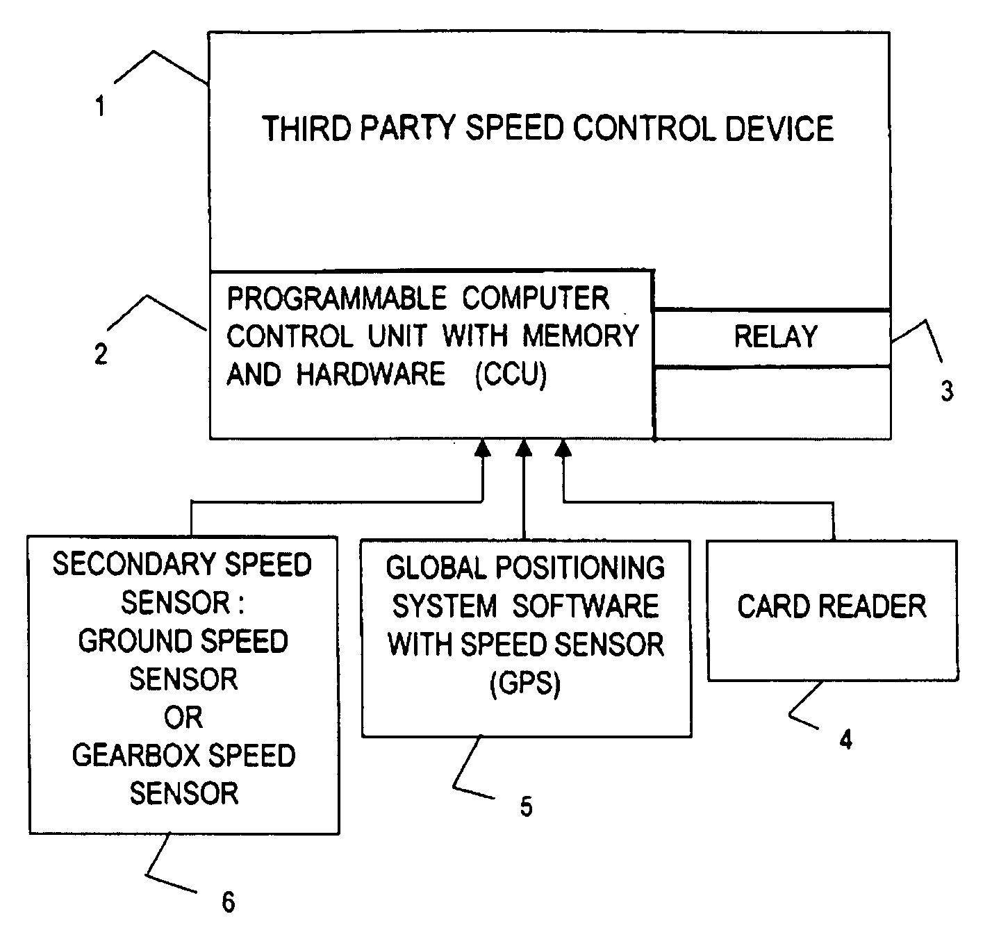
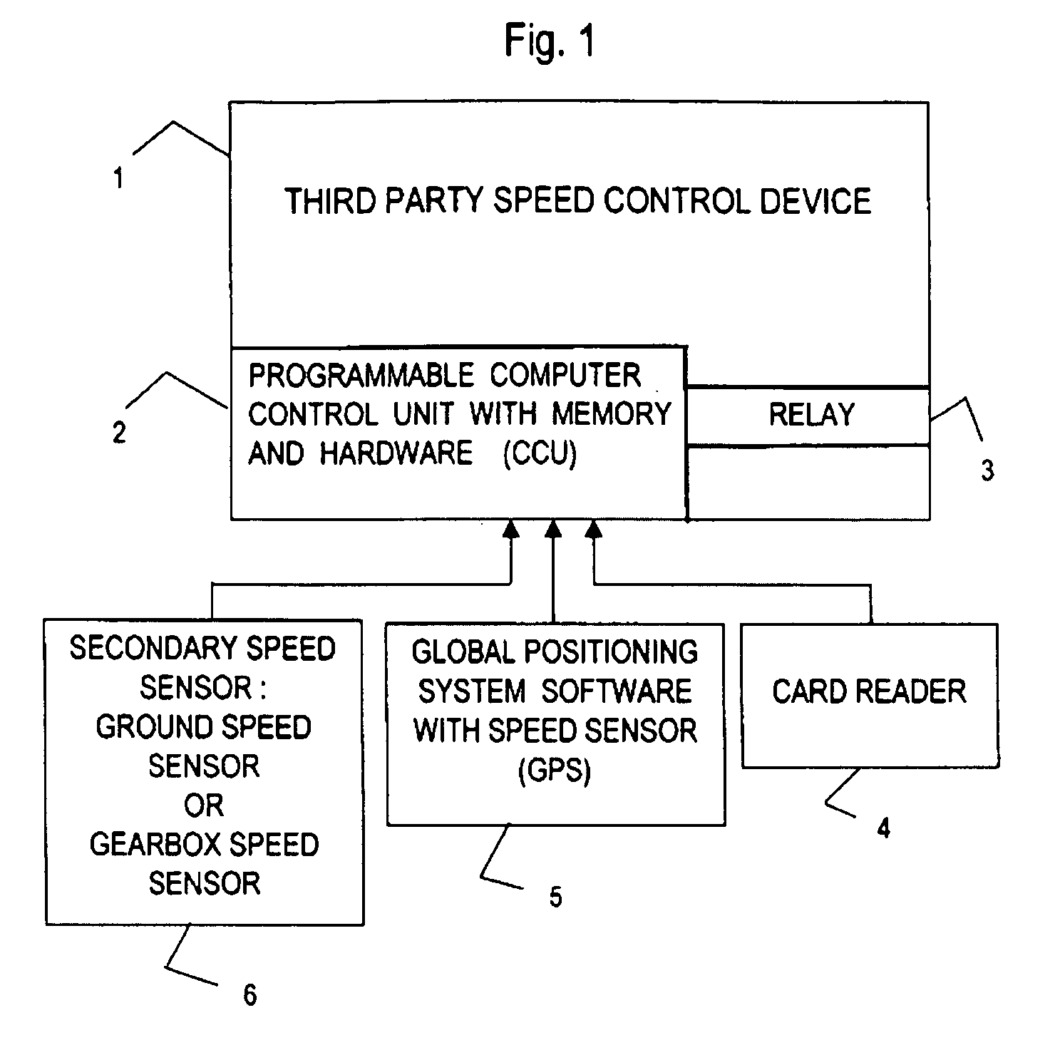
[0040]The present invention will be described with respect to a method and a system for third party speed control device capable of controlling and insisting any operator to obey a third party determining maximum speed that the operator is allowed to operate any vehicle with speed in public places whereby the operator will not be able to override the third party controlling. FIG. 1 shows, schematically the major components of a first embodiment of the invention; there is...


PUM


Abstract

The present invention relates to a system and method of controlling vehicular speed, in particular by a third party, which uses data relating to geography and operator. In some instances, it is desirable to limit the power generated by an engine of a vehicle, to limit the maximum speed of the engine or to have a cruise control function on the vehicle for example. An electronic control unit ECU may be fitted to an engine, whilst a throttle valve is controlled by an operator/driver of a vehicle, this leaves the ECU operable to control the ignition and, where available, the injection, in order to control or adjust the power of the engine. For example, when the engine reaches a predetermined maximum speed, the ECU will control the engine such that some of the spark plugs are not fired and/or that fuel is not injected in every combustion chamber. The present invention seeks to provide an improved speed control device and system for a vehicle. In particular, the present invention seeks to provide an improved speed control device and system for vehicles, which can be subject to environmental and other third party limits. In accordance with a first aspect of the invention, there is provided a speed control device for a vehicle whereby a third party can impose supervisory control upon a specific vehicle and vehicle operator combination which cannot be override by the vehicle operator, the vehicle having a motor operable to provide motive power to the vehicle, a vehicle controller operable to receive speed data of the vehicle, a motor controller operable to control the output of the motor, an interface operable to receive data relating to a specific operator.

Description

FIELD OF THE INVENTION[0001]The present invention relates to a system and method of controlling vehicular speed, in particular by a third party, which uses data relating to geography and operator.BACKGROUND OF THE INVENTION[0002]In some instances, it is desirable to limit the power generated by an engine of a vehicle, to limit the maximum speed of the engine or to have a cruise control function on the vehicle for example. An electronic control unit ECU may be fitted to an engine, whilst a throttle valve is controlled by an operator / driver of a vehicle, this leaves the ECU operable to control the ignition and, where available, the injection, in order to control or adjust the power of the engine. For example, when the engine reaches a predetermined maximum speed, the ECU will control the engine such that some of the spark plugs are not fired and / or that fuel is not injected in every combustion chamber.[0003]Recent developments in the field of automotive electronics now allow these veh...

Claims


Application Information

Patent Timeline
Patent Type & Authority Applications(United States)
IPC IPC(8): G06F7/00G01S1/00G01S19/48
CPCG01S19/52B60K31/0058
Inventor THE, JACOB K.
Owner THE JACOB K
Why Eureka
Try Eureka