System and method for determining position or speed of a commutated DC motor with error correction

a commutated dc motor and error correction technology, applied in the direction of dynamo-electric converter control, dc motor rotation control, instruments, etc., can solve the problems of missing or extra ripple counts, and conventional approaches are generally inefficien

Active Publication Date: 2009-10-08
APTIV TECH LTD
View PDF11 Cites 42 Cited by
  • Summary
  • Abstract
  • Description
  • Claims
  • Application Information

AI Technical Summary

Problems solved by technology

Distortion can arise in the ripple current signal due to rotor (armature) eccentricity, brush seating, magnetic saturation, pulse-width modulation (PWM) of the armature voltage, torque ripple, external mechanical load and other effects which can result in missed or extra ripple counts.
A n

Method used


Image

  • System and method for determining position or speed of a commutated DC motor with error correction
  • System and method for determining position or speed of a commutated DC motor with error correction
  • System and method for determining position or speed of a commutated DC motor with error correction

Examples


first embodiment

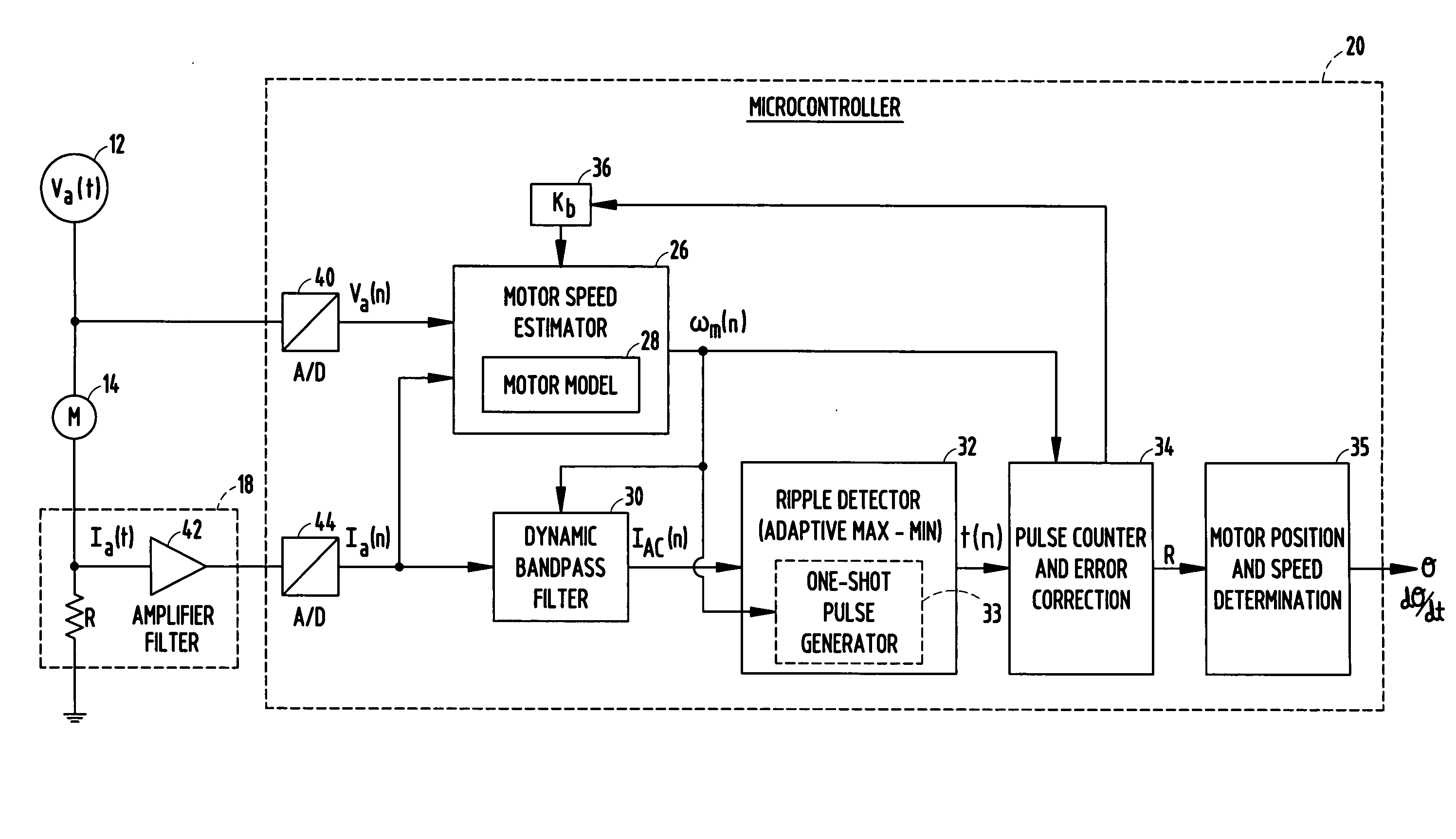
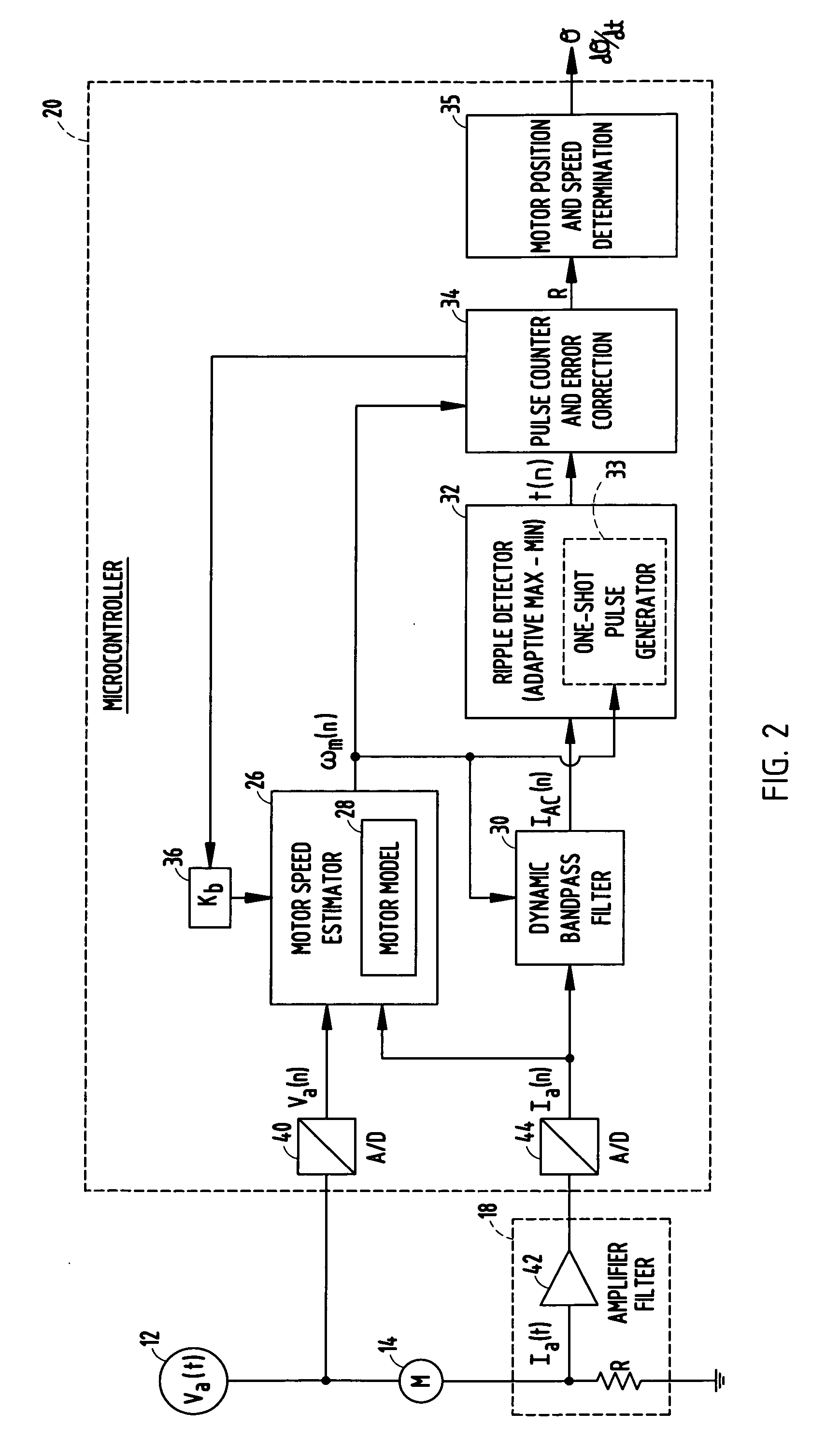
[0025]The dynamic bandpass filter 30 is further illustrated in more detail in FIG. 3, according to a Filter 30 includes a ripple frequency and motor state block 50 for receiving the estimated motor rotational speed ωm and providing the ripple frequency and motor state as outputs to blocks 52 and 56. Block 52 multiplies the ripple frequency by a constant a1, while block 56 multiplies the ripple frequency by a constant a2. Constant a1 represents the index for selection of the high pass filter coefficients in filters 54 and 58 so that the cut-on frequency is a percentage above the ripple frequency. Constant a2 represents the index for the selection of the low pass filter 58 coefficients so that the cut-off frequency is a percentage below the ripple frequency. The output of block 52 is provided along with the digital sensed current Ia to a DC blocking filter 54 which filters out the DC current component such that the AC current IAC with ripple signals pass therethrough. The output of D...

second embodiment

[0026]The dynamic bandpass filter 30 may alternately be implemented as shown in FIG. 4, according to a In this embodiment, the output of block 52 is provided as an input to a low pass filter 58, and the output of block 56 is input to another low pass filter 58. The difference between the outputs of the low pass filters 58 is computed in summing block 60, and the difference output provides for the filtered AC component of ripple current IAC.

[0027]When the control system 20 determines that it is probable that ripple detection error has occurred, it switches to a motor state model 28, shown in one embodiment provided in the motor speed estimator 26. The motor model 28 uses a speed dependent motor voltage Vb to estimate the ripple frequency, where a ratio based on the motor model estimate of the ripple frequency and the actual calculated ripple frequency are evaluated to determine the number of ripple counts that should have been detected. The circuit shown in FIG. 5 represents a motor...


PUM


Abstract

A motor control system and method are provided for detecting current ripple in a commutated DC motor and further determining position and speed of the motor based on the detected ripple current. Ripples in the motor current are detected and a ripple frequency is calculated based on the time between successive ripples. A ripple count between successive frequencies is determined and the ripple count is compared to a threshold value, and an estimated ripple frequency is determined from a motor model when the ripple count exceeds the threshold value. A corrected ripple count is calculated from a ratio of the calculated ripple frequency and the estimated ripple frequency, and motor position and motor speed are determined based on the corrected ripple count.

Description

CROSS-REFERENCE TO RELATED APPLICATION[0001]This application claims the benefit under 35 U.S.C. 35 U.S.C. §119(e) of U.S. Provisional Patent Application No. 61 / 043,266, filed on Apr. 8, 2008, the entire disclosure of which is hereby incorporated herein by reference.TECHNICAL FIELD[0002]The present invention generally relates to a method for detecting ripple current in a commutated DC motor, and more particularly relates to determining position and / or speed of the motor based on the detected ripple current.BACKGROUND OF THE INVENTION[0003]Commutated direct current (DC) motors have an armature current signal that generally includes a DC current signal and an alternating current (AC) signal in the form of current ripples which are the current peaks contained in the motor armature current signal that occur when the armature of the motor rotates. Ripple counting is a well recognized technique that utilizes the AC portion of the armature current signal caused by the commutation process to...

Claims


Application Information

Patent Timeline
IPC IPC(8): G01P3/44G01R31/34G01R23/15
CPCG01P3/44G01P3/48H02P7/2805H02P7/0044H02P7/28H02P6/10H02P7/0094H02P7/04
Inventor SCHNEIDER, PHILIP K.CANALES, SALVADOR A.
Owner APTIV TECH LTD
Why Eureka
Try Eureka