Device and Method for Climate Control

Inactive Publication Date: 2009-10-15
ROBERT BOSCH GMBH
View PDF13 Cites 2 Cited by
  • Summary
  • Abstract
  • Description
  • Claims
  • Application Information

AI Technical Summary

Benefits of technology

[0005]In contrast to this, the climate control device according to the present invention has the advantage that only the driver's footwell is selectively cooled. The temperature of the remaining space surrounding the driver is increased or at least kept stable. Until now, it has been assumed that a drop in the body's core temperature is the factor that initiates the sleep phase when a person becomes drowsy. Yet further investigations have revealed that the reduction of the body's core temperature comes about due to the fact that the blood vessels in the extremities are dilated. The dilation of the blood vessels results in an increased blood circulation in the extremities. The increased blood circulation likewise causes an increased dissipation of heat into the atmosphere. This increased dissipation of heat causes the body's core temperature to drop. This sequence in the human organism may be considered a physiological active chain for inducing sleep. Inducing only a cooling of the person to be kept awake may increase drowsiness in that this possibly even

Problems solved by technology

This increased dissipation of heat causes the body's core temperature to drop.
Inducing only a cooling of the person to be kept awake may increase drowsiness in that this possibly even accelerates the decrease in the body's core temperature.
If the target temperature is not measured even after

Method used


Image

  • Device and Method for Climate Control
  • Device and Method for Climate Control
  • Device and Method for Climate Control

Examples


Embodiment Construction

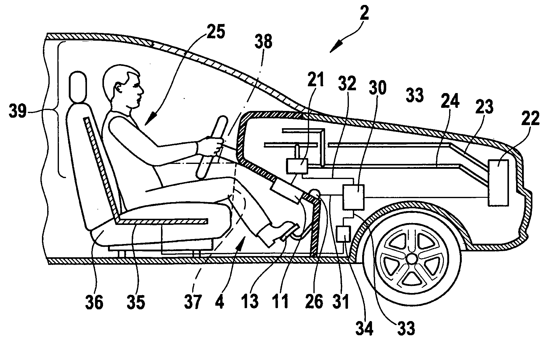
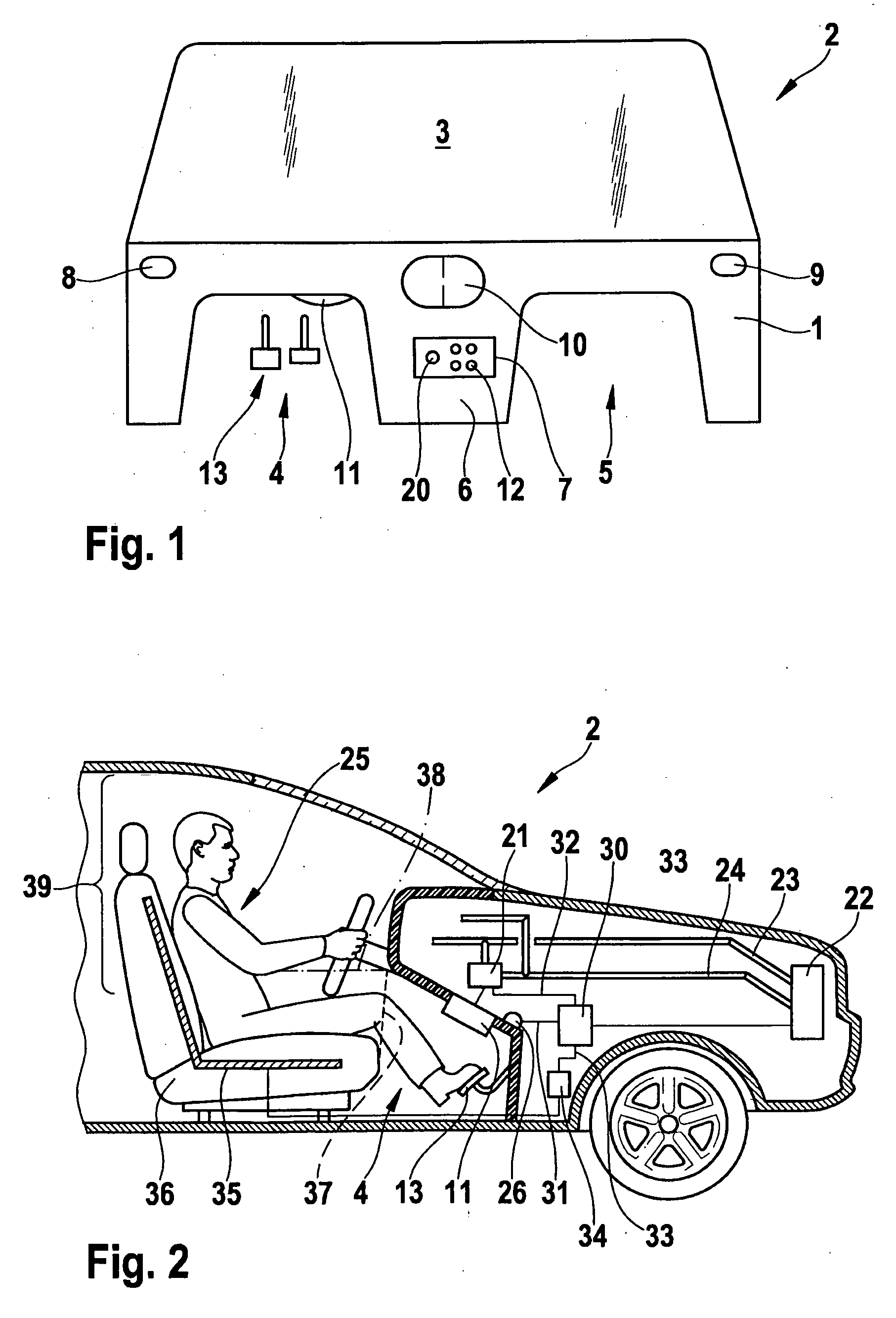
[0017]FIG. 1 shows an instrument panel 1 in a motor vehicle 2 that connects to the lower side of a windshield 3. The instrument panel leaves space for a driver footwell 4 and for a passenger footwell 5. The footwells 4, 5 are separated by a center console 6. Additionally, pedals 13 for control of vehicle 2 are located in driver footwell 4. An operating unit 7 that is used to control the climate in the vehicle is disposed in the region of center console 6 of instrument panel 1. It is connected to a climate control device in the vehicle that is not shown in FIG. 1. The climate control device is connected on the one hand to sensors in the vehicle, on the other hand to an air conditioner, fans, and / or ventilation actuators in the vehicle. To introduce fresh air into the interior of the vehicle, an air inlet 8 is disposed on the left side, an air inlet 9 is disposed on the right side, and an air inlet 10 is disposed in the region of the center console, for example. Additionally, the driv...


PUM


Abstract

A device for climate control includes at least one data interface for outputting first such control data for an actuator unit of an air inlet into a driver footwell such that the footwell is cooled relative to the remaining space surrounding the driver and for outputting second control data to a unit for warming the remaining space surrounding the driver such that the remaining space surrounding the driver is at least partially heated, and thus the physiological active chain that commences when the driver is drowsy is interrupted.

Description

BACKGROUND OF THE INVENTION[0001]1. Field of the Invention[0002]The present invention relates to a device and a method for climate control in a motor vehicle.[0003]2. Description of Related Art[0004]A drowsiness detection in which the driver of a vehicle is monitored by a camera is already known from published European patent document EP 1418082. The recorded image is evaluated to determine whether the driver's eyes are open or closed. If it is detected that the driver is fatigued, the air conditioner of the vehicle is set such that it outputs cold air or that it adds a peppermint aroma to the output air.BRIEF SUMMARY OF THE INVENTION[0005]In contrast to this, the climate control device according to the present invention has the advantage that only the driver's footwell is selectively cooled. The temperature of the remaining space surrounding the driver is increased or at least kept stable. Until now, it has been assumed that a drop in the body's core temperature is the factor that ...

Claims


Application Information

Patent Timeline
IPC IPC(8): B60H1/00
CPCB60H1/00842B60H1/00742B60H1/00807B60H1/00985
Inventor LADSTAETTER, ULRICH
Owner ROBERT BOSCH GMBH
Why Eureka
Try Eureka